
Datasheet


www.apem-idec.eu
D-078
APEM
Switches &
Pilot Lights
Control Boxes
Emergency
Stop Switches
Enabling
Switches
Safety Products
Explosion Proof
Terminal Blocks
Relays & Sockets
Circuit
Protectors
Power Supplies
LED Illumination
Controllers
Operator
Interfaces
Sensors
AUTO-ID
Enabling Switches
HE1B
HE2B
HE3B
HE5B
HE6B
HE2G
HE1G-L
Actuator w/
Plastic Holder
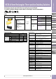
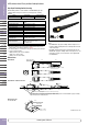
HE5B ø16mm Round Three-position Enabling Switches
• The enabling switches have been designed for industrial purposes.
Use for residential, commercial, or lighting purposes may cause
unwanted electromagnetic disturbances in which case the user may
be required to take adequate mitigation measures. (IEC60947-1,
Clause 5.3)
• Do not assemble or modify the enabling switches and do not disable
the enabling function. Otherwise, failure of accidents may occur.
• When using the enabling switch in a safety related part of a control
system, use the enabling switch properly in accordance with the
safety standards and regulations of the actual machine, system,
and application, of the country or region where the enabling switch
is used. Also, perform a risk assessment before using the enabling
switch.
• Do not disable the safety function of the enabling switch by using
tape, elastic band, or by disguring the rubber boot, otherwise the
loss of enabling switch function may cause serious accidents.
• Perform a risk assessment in actual applications as strong force may
be applied to the switch when depressed to position 3.
• Perform a risk assessment for the shape and structure of the part
where the enabling switch is installed, to prevent unintended opera-
tion of the enabling switch. For example, an enabling switch protrud-
ing from the teach pendant may result in an unintended operation of
the enabling switch.
• Strong force may be applied to a 3-position enabling switch when
pressed to position 3. Provide sufcient strength to the part where
3-position enabling switches will be installed.
• Operator strength is 250N. If the expected operating force exceeds
250N, use a separate actuator with a stoppper.
• Use wires of the proper size to meet voltage and current require-
ments, and solder the wires correctly according to the wiring instruc-
tion described below. If soldering is incomplete, the wire may heat
during operation, causing a re hazard.
• Do not apply excessive force to the enabling switch.
• Follow the wiring instructions mentioned in the instruction manual.
Safety Precautions
Instructions
Operating Instructions
• The enabling switch permits machine operation only while the
enabling switch is manually operated for robot teaching or other
purposes in hazardous areas. Make sure that the control system is
designed to activate the machine only when the enabling switch is at
position 2 (3mm) operating travel.
• To achieve a high level of safety, connect the two contacts of the
3-position switch to a disparity detection circuit (e.g., safety relay
module) (ISO 13849-1, EN 954-1).
• Because two contacts are designed to operate independently, press-
ing the edge of a button turns on one contact earlier than the other
contact, causing a delay in operation. To avoid this, always press the
center of the button.
• When an enabling switch with rubber boot is mounted in a hermet-
ically-sealed control box, a large change in internal air pressure may
cause the rubber boot to inate and deate, affecting the perfor-
mance of the enabling switch. Check periodically to make sure that
the enabling switch operates correctly.
• The edge of rubber boot may stick out if excessive force is applied on
the rubber boot. When such event is anticipated, it is recom mended
to embed the rubber boot in the mounting panel as shown in the
gure below.
• To prevent malfunction of enabling switches without rubber boot, add
extra protection.
Installation Instructions
• If the mounting panel is deformed, waterproof characteristics of the
enabling switch with rubber boot cannot be achieved. Keep sufcient
strength on the mounting panel.
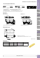
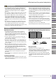
HE9Z-GSH51 Grip Style Enabling Switch Housing
• Recommended Tightening Torque
Parts for tightening Torque
A Head and body 0.8 to 1.2 N·m
B Body and cable gland 2.7 ± 3.3 N·m
C Cable gland 2.7 ± 3.3 N·m
• The recommended tight ening torques of B and C are for the supplied
cable gland. When using another cable gland, refer to the tightening
torque of the cable gland used.
Wiring Instructions
• Applicable wire size: 0.5 mm
2
maximum × 1 pc.
• Solder the terminal at a temperature of 310 to 350°C within 3 sec-
onds using a soldering iron. Sn-Ag-Cu type is recommended when
using lead-free solder. Do not use ow or dip soldering.
• When soldering, take care not to touch the enabling switch with
the soldering iron. Also ensure that no tensile force is applied to the
terminal. Do not bend the terminal or apply excessive force to the
terminal.
• Use non-corrosive liquid rosin as soldering ux.
Head Body
Cable Gland
A
B C