
Datasheet


General Information
Enabling Switches
419
USA: 800-262-IDEC Canada: 888-317-IDEC
Overview X Series E-Stops Door Interlock Switches Enabling Switches Barriers AS-Interface Safety at Work
General Information
Safety Precautions
In order to avoid electric shock or fi re, turn power off before installation,
removal, wire connection, maintenance or inspection of switch.
Follow specifi cation when installing. Improper electrical load may damage
switch, cause electric shock, or fi re.
•
•
Use proper wire diameter to meet voltage and current requirements. Using
improper wires or incomplete soldering may cause fi re due to abnormal heat
generation.
•
Installation Precautions
HE2B
M3 nut is inside the rubber cover.
HE2B/HE3B
A change in internal air pressure may cause the rubber boot to expand and
shrink on an enabling switch that has the rubber boot sealed. This may affect
the performance of the switch. Periodically check to ensure that the enabling
switch is operating correctly.
•
•
If the panel is not level when mounting an enabling switch, the waterproof
feature cannot be guaranteed.
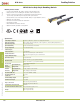
HE3B
The rubber boot has a tab to be used for orientation. When making a position-
ing hole in a panel, do not make a hole in the rubber boot, or the waterproof
feature cannot be guaranteed. When the positioning hole is not on the panel,
remove the tab, but do not make a hole in the rubber boot.
When tightening the locking ring, secure the fl ange to prevent the enabling
switch from rotating. In applications where the enabling switch is to be
rotated, mount the switch in a recess on the panel as shown.
Locking Ring
Anti-rotation Ring
Positioning
Projection
Mounting Panel
•
•
•
Wiring Precautions
HE1B/HE2B/HE3B
Applicable wire size is 0.5mm
2
(20AWG) (maximum) / 1 line.
When soldering the terminal, solder at a temperature of 260°C within 3
seconds. Use non-corrosive liquid rosin as soldering fl ux.
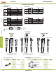
HE1G
Wire Stripping Information
Wire Length Terminal Number 1-4 Terminal Number 5-8
L1, L2 (mm) L1=40mm L2=27mm
L3 (mm) L3=6mm
Cable Gland
Base
Terminal No.
L3
L1
L3
L2
ø15.875
Applicable Wire Size:0.14 to 1.5mm
2
(24 - 16AWG, one wire per terminal)
•
•
•
•
Recommended Torque
cover
base
base
cover
base
(M4 screw x 3)
See Drawing Above Recommended Torque
Rubber Boot & Base A 1.2±0.1Nm
Connector & Grip Switch B 4.0±0.3Nm
Connector C 4.0±0.3Nm
Terminal Screw D 0.5±0.6Nm
Do Not Remove E
•
Use Precautions
HE2B/HE3B/HE1G
To ensure the highest level of reliability connect both contacts to a monitoring
device such as a safety relay.
•
HE1B/HE2B/HE3B
When installing the enabling switch ensure that it cannot be accidently
activated. For example, a protrusion from a teaching pendant could cause the
enabling switch to be activated by the weight of the teaching pendant.
•