
Datasheet


HE1G Series
Enabling Switches
417
USA: 800-262-IDEC Canada: 888-317-IDEC
Overview X Series E-Stops Door Interlock Switches Enabling Switches Barriers AS-Interface Safety at Work
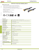
Part Numbers
Part Numbers 3 Position Switch Monitor Switch Emergency Stop Pushbutton Momentary Pushbutton
HE1G-21SM 2 Contacts Yes (1NC) No No
HE1G-20ME 2 Contacts No Yes (2NC) No
HE1G-21SMB 2 Contacts Yes (1NC) No Yes (1NO)
HE1G-20MB 2 Contacts No No Yes (2NO)
Ratings
Contact Ratings
Rated Insulation Volute (Ui) 250V
Thermal Current (lth) 3A
Rated Operating Voltage (Ue) 30V 125V 250V
Rated Operating
Current (le)
3 Position Switch
(Terminal No.1-2, 3-4)
AC
Resistive Load (AC-12) – 3A 0.5A
Inductive Load (AC-15) – 1.5A 0.5A
DC
Resistive Load (DC-12) 2A 0.4A –
Inductive Load (DC-13) 1A 0.22A –
Monitor Switch
(Terminal No. 5-6 of
HE1G-21SM)
AC
Resistive Load (AC-12) –2A1A
Inductive Load (AC-15) – 1A 0.5A
DC
Resistive Load (DC-12) 2A 0.4A 0.2A
Inductive Load (DC-13) 1A 0.22A 0.1A
Emergency Stop
Pushbutton
(Terminal No. 5-6, 7-8
of HE1G-20ME)
AC
Resistive Load (AC-12) –––
Inductive Load (AC-15) – – 0.5A
DC
Resistive Load (DC-12) –––
Inductive Load (DC-13) – – 0.1A
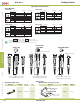
Contact Structure
3 Position Switch 2 Contacts
Monitor Switch 0 or 1 Contact
Emergency Stop Pushbutton 0 or 2 Contacts
Momentary Pushbutton 0 to 2 contacts
The minimum load (reference) = AC/DC3V • 5mA (for reference only.