
Datasheet

www.apem-idec.eu
D-087
APEM
Switches &
Pilot Lights
Control Boxes
Emergency
Stop Switches
Enabling
Switches
Safety Products
Explosion Proof
Terminal Blocks
Relays & Sockets
Circuit
Protectors
Power Supplies
LED Illumination
Controllers
Operator
Interfaces
Sensors
AUTO-ID
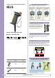
Enabling Switches
HE1B
HE2B
HE3B
HE5B
HE6B
HE2G
HE1G-L
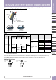
Actuator w/
Plastic Holder
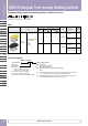
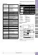
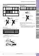
HE2G Grip Style Three-position Enabling Switches
Instructions
Operating Instructions
• This grip style three-position enabling switch is a device used for
enabling a machine such as robots when teaching the machine in a
hazardous area manually. Congure the enabling system so that the
machine can operate when the switch is in position 2 and an sepa-
rate start switch is required to initiate the system.
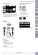
• To achieve a high level of safety, connect the two contacts of the
3-position switch to a disparity detection circuit (terminal No. NO1-C1
and NO2-C2) to a discrepancy detection circuit such as a safety relay
module. (ISO13849-1/ EN954-1)
• The base and the plastic part of rubber boot frame are made of
glass-reinforced ABS/PBT. The rubber boot is made of silicone rubber
or NBR/PVC polyblend. The screw is made of iron. When cleaning the
grip style three-position enabling switch, use a detergent compatible
with the materials.
• When adding momentary pushbutton switch and key selector switch,
do not connect NO and NC contacts of a microswitch to different volt-
ages or different power sources to prevent a dead short-circuit.
• When operating a additionally installed key selector switch, be sure to
fully insert the key. Otherwise, failure may occur.
• The rubber boot may deteriorate depending on the operating environ-
ment and conditions. When the rubber boot is deformed or cracked,
replace with new ones.
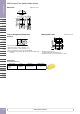
Wiring Instructions
• Solder the terminal at a temperature of 310 to 350°C within 3 sec-
onds using a soldering iron. Sn-Ag-Cu type is recommended when
using lead-free solder. Do not use ow or dip soldering.
• When soldering, take care not to touch the enabling switch with
the soldering iron. Also ensure that no tensile force is applied to the
terminal. Do not bend the terminal or apply excessive force to the
terminal.
• Use non-corrosive liquid rosin as soldering ux.
• Because the terminal spacing is narrow, use protective tubes or heat
shrinkable tubes to avoid burning of wire coating or short circuit.
• When using a stranded wire, make sure that adjoining terminals are
not short-circuited
• with protruding core wires.
• Use copper Wire 60/75 degree C only. (UL508)
• The wiring has to be installed according to GS-ET-22, 4.2.6.
• The enabling switches have been designed for industrial purposes.
Use for residential, commercial, or lighting purposes may cause
unwanted electromagnetic disturbances in which case the user may
be required to take adequate mitigation measures. (IEC60947-1,
Clause 5.3)
• Do not assemble or modify the enabling switches and do not disable
the enabling function. Otherwise, failure of accidents may occur.
• When using the enabling switch in a safety related part of a control
system, use the enabling switch properly in accordance with the
safety standards and regulations of the actual machine, system,
and application, of the country or region where the enabling switch
is used. Also, perform a risk assessment before using the enabling
switch.
• Do not hold the enabling switch to position 2 using tapes or strings
Otherwise the loss of enabling switch function may cause serious
accidents.
• Do not use with the grip switch installed on a machine.
• Use wires of the proper size to meet voltage and current require-
ments.
• Do not apply excessive force to the enabling switch.
• Make sure that dust, water and oil do not enter the grip switch during
wiring.
• Be sure to choose cables according to the operating environment.
• If multiple safety components are wired in series, the Performance
Level to EN ISO 13849-1 will be reduced due to the restricted error
detection under certain circumstance.
• The entire concept of the control system, in which the safety compo-
nent is integrated, must be validated to EN ISO 13849-2.
Safety Precautions