
Datasheet

www.apem-idec.eu
D-085
APEM
Switches &
Pilot Lights
Control Boxes
Emergency
Stop Switches
Enabling
Switches
Safety Products
Explosion Proof
Terminal Blocks
Relays & Sockets
Circuit
Protectors
Power Supplies
LED Illumination
Controllers
Operator
Interfaces
Sensors
AUTO-ID
Enabling Switches
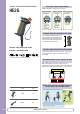
HE1B
HE2B
HE3B
HE5B
HE6B
HE2G
HE1G-L
Actuator w/
Plastic Holder
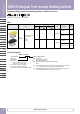
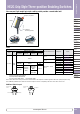
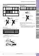
HE2G Grip Style Three-position Enabling Switches
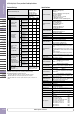
Contact Ratings
Rated Insulation Voltage (Ui)
250V (momentary
pushbutton and key
selector: 125V) /
30V (with pilot light)
Rated Thermal Current (lth)
3A (emergency stop
switch: 5A)*
Rated Voltage (Ue) 30V 125V 250V
Rated Current
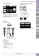
Grip Style Enabling Switch
3-position switch
(Terminal No.
NO1-C1/A1-B1,
NO2-C2/A3-B3)
AC
Resistive
Load (AC-12)
— 1A 0.5A
Inductive
Load (AC-15)
— 0.7A 0.5A
DC
Resistive
Load (DC-12)
1A 0.2A —
Inductive
Load (DC-13)
0.7A 0.1A —
Monitor Switch
(NC contact)
(Terminal No.
31-32/A2-B2)
AC
Resistive
Load (AC-12)
— 2.5A 1.5A
Inductive
Load (AC-15)
— 1.5A 0.75A
DC
Resistive
Load (DC-12)
2.5A 1.1A 0.55A
Inductive
Load (DC-13)
2.3A 0.55A 0.27A
Switch & Pilot Light
Emergency Stop
Switch
XA1E-BV3U02
(Terminal No.1-2/A1-
B1, 1-2/A2-B2)
AC
Resistive
Load (AC-12)
— 5A 3A
Inductive
Load (AC-15)
— 3A 1.5A
DC
Resistive
Load (DC-12)
2A 0.4A 0.2A
Inductive
Load (DC-13)
1A 0.22A 0.1A
Momentary Pushbutton
Key Selector Switch
AB6M-M2PLW,
AS6M-2KT2PA
(Terminal No.C1/B1,
NO1/B2, NC1/B3, C2/
A1, NO2/A2, NC2/A3)
AC
Resistive
Load (AC-12)
— 0.5A —
Inductive
Load (AC-15)
— 0.3A —
DC
Resistive
Load (DC-12)
1A 0.2A —
Inductive
Load (DC-13)
0.7A 0.1A —
UP9 Pilot Light
UP9P-2498G
(Terminal No. +, –)
Rated operating
voltage: 24V DC ±10%
Rated current: 15mA
Note: Minimum applicable load (reference value): 3V AC/DC, 5 mA
(Applicable range is subject to the operating conditions and load.)
*Operating temperature for internal connectors:
–25°C min., 40°C max. 2.5A (12 to 19 poles), 2A (20 to 22 poles)
40°C min., 50°C max. 2.5A (8 to12 poles), 2A (13 to 22 poles)
50°C min., 60°C max. 2.5A (6, 7 poles), 2A (8 to13 poles), 1.5A (14 to 22
poles)
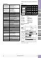
Specifications
Applicable Standards
IEC60947-5-1
EN60947-5-1 (TÜV approval)
JIS C8201-5-1
IEC60847-5-8, EN60947-5-8(TÜV approval)
GS-ET-22(TÜV approval)
UL508 (UL recognized)
CSA C22.2 No.14 (c-UL recognized)
GB14048.5 (CCC approval)
KS C IEC60947-5-1/S1-G-1 (KOSHA approval)
Applicable Standards
for Use
ISO12100/EN ISO12100
IEC60204-1/EN60204-1
ISO11161/EN ISO11161
ISO10218-1/EN ISO10218-1
ANSI/RIA/ISO10218-1
ANSI/RIA R15.06, ANSI B11.19
ISO13849-1/EN ISO13849-1
Operating Temperature
Silicon rubber boot:
–25 to 60°C (no freezing)
NBR/PVC Polyblend rubber boot:
–10 to 60°C (no freezing)
Relative Humidity 45 to 85% (no condensation)
Storage Temperature –40 to +80°C (no freezing)
Pollution Degree 3
Contact Resistance 50 mΩ maximum (initial value)
Insulation Resistance
Between live and dead metal parts:
100 MΩminimum (500V DC megger)
Between terminals of different pole:
100 MΩminimum (500V DC megger)
Impulse Withstand
Voltage
(Solder terminal)
Grip style enabling switch/emergency stop switch:
2.5 kV
Momentary pushbutton/key selector switch: 1.5 kV
Pilot light: 500V AC, 1 minute (between live and dead
parts)
(Internal connector)
Grip style enabling switch/emergency stop switch/
momentary pushbutton/key selector switch: 1.5 kV
Electric Shock
Protection Class
Class II (IEC 61140) (With pilot light: class III)
Operating Frequency 1,200 operations per hour
Mechanical Durability
Position 1 → 2 → 1:
1,000,000 operations minimum
Position 1 → 2 → 3 → 1:
100,000 operations minimum
Electrical Durability
100,000 operations minimum (rated load)
1,000,000 operations minimum (24V AC/DC, 100 mA)
Shock Resistance
Operating extremes: 150 m/s
2
Damage limits: 1,000 m/s
2
Vibration Resistance
Operating extremes:
5 to 55 Hz, amplitude 0.5 mm minimum
Damage limits:
16.7 Hz, amplitude 1.5 mm minimum
Applicable Wire
Solder terminal: 0.5 mm
2
maximum
Internal connector: 0.05 to 0.86 mm
2
(AWG18 to 30)
Applicable Wire Size
Solder terminal: 0.5 mm
2
Internal connector: 0.05 to 0.86 mm
2
(AWG18 to 30)
(AWG22 between switch and connector)
Applicable Cable Outside diameter: ø4.5 to 10 mm
Conduit Port Size M16 (cable gland is supplied)
Terminal Tensile Strength
20N minimum
Degree of Protection
Without switch/pilot light IP67/66
With switch/pilot light IP65
Conditional Short-
circuit Current
50A (250V) (Use 250V/10A fast-blow fuse for short
circuit protection.)
Direct Opening Force 60N minimum (monitor switch)
Operator Strength
500N minimum (when pressing the entire button
surface)
Free Fall 1.0m 1 fall (IEC 60068-2-32 compliant)
Weight (approx.)
HE2G-21SH: 140g
HE2G-21SH-P-0/-21SC: 145g
HE2G-21SHE/-21SC-P-0: 150g
HE2G-21SH-L-L/-21SHE-P-0/-21SCE: 155g
HE2G-21SH-L-K/-21SCE-P-0: 160g
HE2G-21SHE-L-L/-21SC-L-L: 165g
HE2G-21SHE-L-K/-21SC-L-K: 170g
HE2G-21SCE-L-L: 175g
HE2G-21SCE-L-K: 180g