
Owner manual


LOGIC
5-152
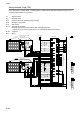
Wiring example (Logic 13A)
In the case where 1 selector switch, 1 enabling switch, 1 interlock switch with solenoid (spring lock type), and 2
emergency stop switches are connected.
S1 :Selector switch
S2 :Enabling switch
S3, 4 :Interlock switch with solenoid (spring lock type)
S5, 6 :Emergency stop switch
S7, 8 :Start switch
S9, 10 :Solenoid control switch
(Pressing the solenoid control switches after closing the guard door,
contacts 41-42 and 51-52 of S3 and S4 turn on, allowing the SafetyOne to restart.)
K1 to 4 :Contactor
M1, 2 :Motor
Fuse
V+
X0
X1
X2
X3
T0
T1
T2
T3
X5
X6
X7
T5
T6
T7
X10
T10
S5
S6
X4
T4
X11
T11
X12
T12
X13
T13
X14
T14
X15
T15
K1 K2
K3 K4
X16
S7
X17
S1
S2
K1
V-
Y4
Y5
Y6
Y7
Y10
Y11
Y12
Y13
Y14
Y15
Y17
Y20
Y0
Y16
K2Y1
K3Y2
K4Y3
To
PLC
FE
24V DC
0V DC
SafetyOne
S8
Guard open
11
12
51
5242 A1(-)
A2(+
)
41
S3
21
22
S9
S10
Guard open
11
12
51
5242 A1(-)
A2(+
)
41
S4
21
22
Interlock switch with solenoid
(spring lock type)
Interlock switch with solenoid
(spring lock type)
Actuator
Actuator
K2
K1
M1
K4
K3
M2