
Instruction Manual
5-37
X10
X11
T10
T11
X12
T12
X13
T13
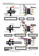
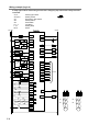
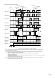
When connecting multiple emergency stop switches
in series
X0
X1
T0
T1
X4
T4
X5
T5
When not using some safety inputs
24V DC
X10
X11
T10
T11
X12
T12
X13
T13
0V DC
Y20
Y17
注)
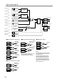
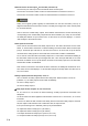
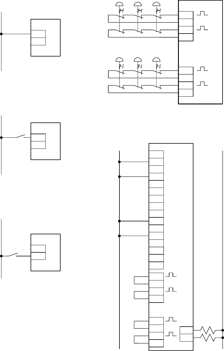
NOTE: In Logic 4,the muting lamp output terminals
(Y17 and Y20) detect that connected indicator lights
are disconnected or unconnected.
When not using the muting function, connect a resistor
across these terminals.
If no resistor is connected, then the SafetyOne detects
any wiring errors and locks out operations.
X16
X17
24V DC
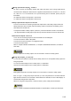
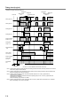
When not using the start switch
(Auto start)
X16
X17
24V DC
When not detecting the welding of start
switch
(Manual start)
X16
X17
24V DC
When detecting the welding of start
switch
(Control start)
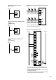
S9
S9
X6
T6
X7
T7
X2
X3
T2
T3
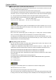
NOTE: Applicable safety performance is dependent
upon each system configuration.