
Instruction Manual
5-18
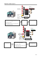
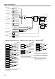
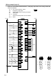
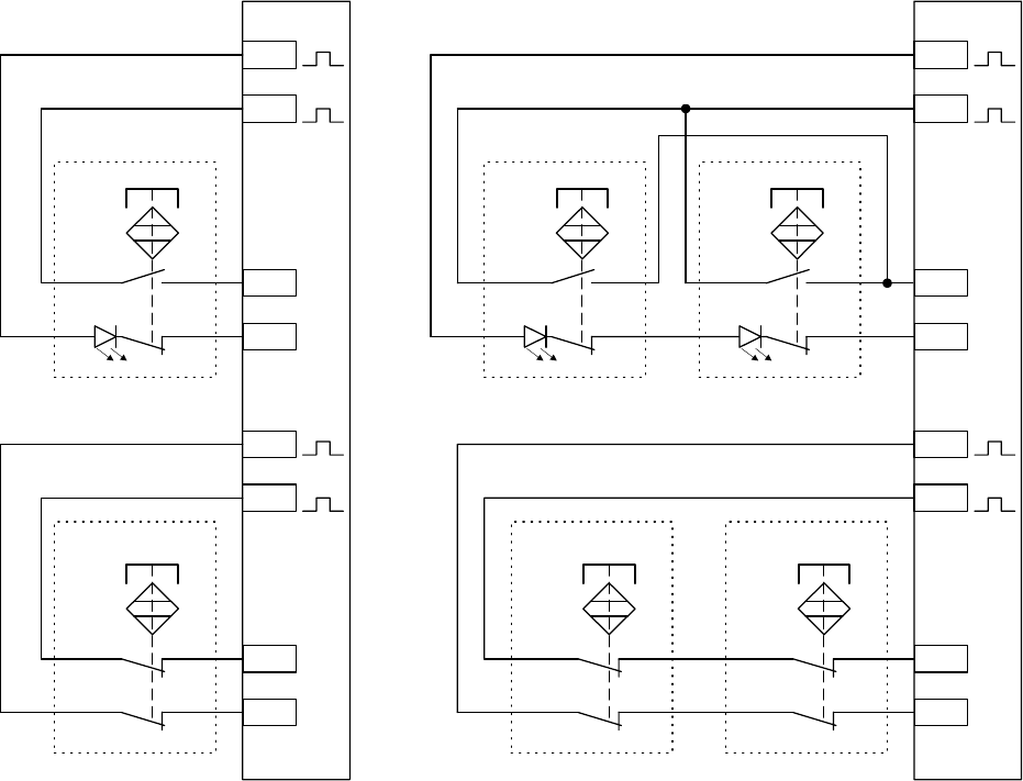
In case of using IDEC non-contact interlock switches HS7A series
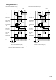
Note 1) Illustration of contacts with magnet present.
Note 2) X0 to X7 (T0 to T7) function as dual channel NO/NC inputs and can be connected to the HS7A-DMC59□(1NO+1NC
Contact,with LED・without LED) or HS7A-DMP50□(1NO+2NC Contact, with LED・without LED).
Note 3) X10 to X13 (T10 to T13) function as dual channel direct opening inputs and can be connected to the HS7A-DMC790□
(
2NO Contact, without LED) or the HS7A-DMP700 i2NO+1NC Contact, without LED).
Same terminals functioning as dual channel direct opening inputs can be connected it in the case of another logic.
Note 4) In the case to connect HS7A-DMC790□ or HS7A-DMP700□, applicable safety performance depends on each
system configuration.
Note 5) In the case to connect an LED type using dual channel NO/NC inputs, The maximum. number of connectable
non-contact
interlock switches per one input is two. iSupply voltage of 24VDC or more. j
In the case of connecting without LED type at dual channel NO/NC inputs, The maximum. number of connectable
non-contact interlock switches per one input is six.
Note 6) Do not connect LED type at dual channel direct opening, but in this case connect without LED type maximum number
of connectable non-contact interlock switches per one input is six.
Note 7) In the case connecting two non-contact interlock switches per one input, applicable safety performance depends upon
the system configuration.
S1
X0
X1
T0
T1
WH
BN+
BK
BU
S5
X10
X11
T10
T11
WH
BN+
BK
BU
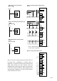
S1
X0
X1
T0
T1
WH
BN+
BK
BU
S5
X10
X11
T10
T11
白
BN+
BK
BU
S2
WH
BN+
BK
BU
S6
WH
BN+
BK
BU
S1、2 : HS7A-DMC59□(1NO+1NC Contact, with LED・without LED) or
HS7A-DMP50□(1NO+2NC Contact, with LED・without LED)
S5、6 : HS7A-DMC790□(2NO Contact, without LED) or
HS7A-DMP700□(2NO+1NC Contact, without LED)
・Case to connect 2 non-contact interlock switches
using 1 safety input