
Instruction Manual
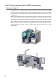
5-12
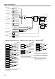
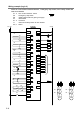
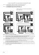
Logic circuit (logic 2)
S1
OS1
&
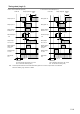
Dual Channel
NO/NC
Dual Channel
Direct Opening
Dual Channel
Direct Opening
Single Channel
Monitor
Single Channel
Monitor
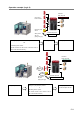
Ex ter nal Dev ic e
Monitor
EDM
Ex ter nal Dev ic e
Monitor
EDM
Control
Start
Control
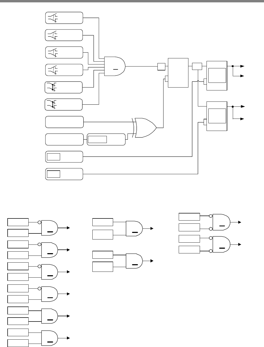
T0, X0, T1, X1
T2, X2, T3, X3
T4, X4, T5, X5
T6, X6, T7, X7
T12, X12, T13, X13
T10, X10, T11, X11
T14, X1 4
T15, X1 5
X16
X1 7
Safety input 1
Safety input 6
Safety input 5
Safety input 4
Safety input 3
Safety input 2
Start input 1
Start input 2
External device
monitor 2
External device
monitor 1
Hold
Trigger
Self-hold
function
Hold
EDM
OSSD
with
Off delay
Hold
EDM
OSSD
with
Off delay
Y0
Y1
Y2
Y3
Safety output 1
Safety output 2
Dual Channel
NO/NC
Dual Channel
NO/NC
Dual Channel
NO/NC
=2k+1
OS1
OS1
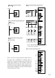
Y12
Y13
X1
X0
Y4
X3
X2
Y5
X5
X4
Y6
X7
X6
Y7
X1 1
X1 0
Y10
X1 3
X1 2
Y11
●Monitor output for safety input ●Monitor output for safety output ●Solenoid output
S1
Y0,Y1
Y17
S1
Y2,Y3
Y20
Y0,Y1
Y2,Y3
Monitor for
safety input 1
Monitor for
safety input 2
Monitor for
safety input 3
Monitor for
safety input 4
Monitor for
safety input 5
Monitor for
safety input 6
Monitor for
safety output 1
Note2:
Monitor outputs for safety output 1 and
2 are turned OFF immediately
independent of the set OFF-delay time.
Note3:
In Run state, when the safety outputs
are OFF and 1 or more safety inputs
are off, the solenoid outputs are turned
ON.
When all safety inputs are ON, the
solenoid outputs are turned OFF,
Although start input is OFF.
(Note2)
(Note3)
&
&
&
&
&
&
&
&
&
&
Monitor for
safety output 2
(Note2)
Note1:
When X
n
is OFF and X
n+1
is ON, the monitor
output for safety input is turned on.
(n = 0,2,4,6)
(Note1)
(Note1)
(Note1)
(Note1)