
Instruction Manual

4-1
Chapter4 BASIC OPERATIONS
This chapter describes the basic operations of SafetyOne. Make proper use of the
SafetyOne by thoroughly familiarizing yourself with the basic operations and functions.
Internal states
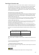
The SafetyOne operates in five internal states, as shown in Table 4.1.
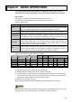
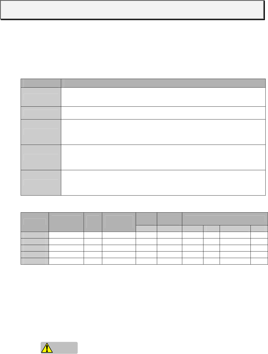
The LED display and output status for each state are shown in Table 4.2.
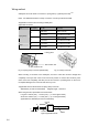
Table 4.1 Internal states
State Description
Initial
This is the state during which initial processing is performed immediately after power is
supplied to SafetyOne. During this state, the internal circuits are checked and the LED
displays and lights indicate operation confirmation (blinking) for about 6s.
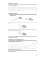
Run
This is the state during which the SafetyOne operates normally. Logic processing
continues without failures or wiring errors.(Refer to "Chapter 5 LOGIC" for details.)
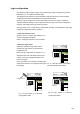
Configuration
This is the state for configuring the logic and OFF-delay timer values.
Executing the determined configuration procedure enables the desired logic and
OFF-delay timer value and restores the SafetyOne to the Run state. (Refer to "Logic
configuration" and "Timer configuration" in this chapter for details.)
Protection
The SafetyOne transitions to this state when there is input monitor error in the dual
channel input, EDM input or muting input. After the cause that generated the
Protection state is removed, the unit is restored to the Run state. (Refer to "Canceling
the Protection state" in this chapter for details.)
Stop
The SafetyOne transitions to this state when a failure or other error occurs in an
external device or internal circuit. After the cause that generated the Stop state is
removed, the Stop state can be canceled by restarting the SafetyOne (power on
again). (Refer to "Canceling the Stop state" in this chapter for details.)
Table 4.2 LED display and output status for each state
Safety
output
Solenoid/
lamp output
Monitor output
State
Logic
LED
Error
LED
Timer
LED
Y0…Y3 Y17,Y20 Y4…Y13 Y14 Y15 Y16
Initial (1) (1) (1) □
OFF
□
OFF
□
OFF
■
ON
■
ON
□
OFF
Run Selected number Blank Selected number (2) (2) (2) □
OFF
□
OFF
■
ON
Configuration (3) “C” (3) □
OFF
□
OFF
□
OFF
□
OFF
■
ON
□
OFF
Protection Selected Number “1” Selected number □
OFF
□
OFF
(4) □
OFF
■
ON
□
OFF
Stop Blank (5) Blank □
OFF
□
OFF
□
OFF
■
ON
■
ON
or □
OFF
□
OFF
(1) Random display in Initial state
(2) LED display and outputs corresponding to selected logic
(3) Blinking display of selected logic number and timer value LED
(4) The input LEDs and monitor outputs corresponding to the input which occurred before the
error become pulse output. For the other LEDs and monitor outputs, the LED indications
and monitor outputs are kept from just before the Run state.
(5) Display the error number occurred.
Refer “Chapter2 PRODUCT SPECIFICATIONS” for detail information of LED display.
Caution
When the state changes to the Run state from another state, solenoid/lamp outputs (Y17, Y20)
are turned ON for 1s maximum. Be wary of the behavior of connected devices.