
Instruction Manual
2-12
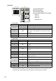
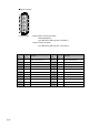
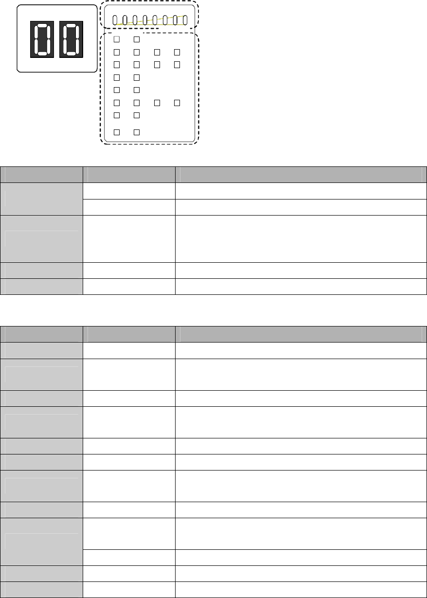
Indicators
0.1.5125
15 30
SAFE- IN
TIMER
(S)
SAFE- OUT
SOLENOID
-OUT
STAR T- IN
X0 X1
X2 X3
X4
X5
X6 X7
X10 X11
X12 X13
X14 X15
X16 X1 7
Y0 Y1
Y2 Y3
Y17 Y20
LOGIC ERROR
(1) Logic LED
Indication Status Descriptions
ON
The selected logic is in Run or Protection state.
“1”... “8”
Blink The selected logic is in Configuration state.
“E” Blink
The selected logic has Configuration error
(The logic is not selected or more than one logic is
selected.)
Random pattern ON/Blink Initializing (Initial state)
Blank OFF Error (stop state)
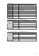
(2) Error LED
Indication Status Descriptions
“1” ON
Input monitor error (Protection state)
“2” ON
Wiring error at safety inputs or error in safety input
circuits
“3” ON Wiring error at start inputs or error in start input circuits
“4” ON
Wiring error at safety outputs or error in safety output
circuits
“5” ON Muting lamp error (disconnection) (Logic4 only)
“6” ON Power supply error or internal power supply circuit error
“7” ON
Internal error, power supply error or internal power
supply circuit error
“9” ON EMC disturbance
ON
Configuration procedure is in progress (Configuration
state)
“C”
Blink Configuration is valid
Note
(Configuration state)
Random ON/Blink Initializing (Initial state)
Blank OFF Normal operation (Run state)
Note. Blinks for 1 to 5 seconds after the enter button is pressed. Releasing the button during
blinking activates the setting. The blinking LED becomes ON if the button is pressed for more
than 5 seconds, and the setting becomes invalid even after the button is released.
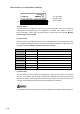
(1) (2)
(
4
)
(3)
(1) Logic LED (green)
(2) Error LED (red)
(3) Timer LED (green)
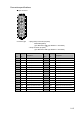
(4) Input/Output status LED (orange)
-SAFE-IN
-START-IN
-SAFE-OUT
-SOLENOID-OUT