
Instruction Manual

5-74
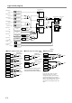
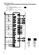
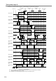
● Start inputs: X12, X13, X16, and X17
X12 is used to control the start of safety outputs 1 and 2 as a “control start” that detects welding of
the start switch. X12 is a start input for safety input 1.
X13 is used to control the start of safety outputs 1 and 2 as an “auto start” which does not use the
start switch, or a “manual start” which does not detect welding of the start switch. X13 is a start
input for safety inputs 2, 3, 4, and 5. X13 is used for a partial stop function.
X16 is used to control the start of safety outputs 1and 2 as a “control start” that detects welding of
the start switch. X16 is a start input for safety inputs 2 and 3. X16 is a partial stop function.
X17 is used to control the start of safety output 2 as a “control start” that detects welding of the
start switch. X17 is a start input for safety inputs 4 and 5. X17 is used for a partial stop function.
When X12 changes from OFFONOFF (the ON state of X12 must be on between 0.1s to 5s)
while the devices connected to safety input 1 are in the safe state, the function output of the
self-hold function 1 is turned ON.
When X13 is ON (the ON state of X13 must be on greater than 0.1s) or X16 changes from
OFFONOFF (the ON state of X16 must be on between 0.1s to 5s) while the devices
connected to safety inputs 2 and 3 are in safe state, the function output of the self-hold function 2
is turned ON.
When X13 is ON (the ON state of X13 must be on greater than 0.1s) or X17 changes from
OFFONOFF (the ON state of X17 must be on between 0.1s to 5s) while the devices
connected to safety inputs 4 and 5 are in the safe state, the function output of the self-hold
function 3 is turned ON.
When the functional output of the self-hold function 1 and 2 are ON, the start condition of the
safety output 1 are established.
When the functional output of the self-hold functions 1, 2, and 3 are ON, the start condition of
safety output 2 is established.
Note: If both sets of X13 and X16, or X13 and X17 are turned ON at the same time, the SafetyOne
will detect an error. As a result, the error LED displays “3” and the state changes to the Stop state.
Use only 1 set of X13 or X16(X17) at a time and never use both together.
Note: Do not use T12 and T13.
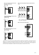
●Safety outputs (with OFF-delay timer): Y0 to Y3
Y0 to Y3 function as safety outputs with the OFF-delay timer. When the timer is set to “0s”
(indication “1”), the safety outputs are shut OFF immediately.
Y0 and Y1: Safety output 1
Y2 and Y3: Safety output 2
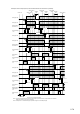
Warning
When 1 contact of the dual channel input corresponding to safety output 2 (safety inputs 4 or 5) is
turned OFF, safety output 2 is turned OFF immediately after the preset time of the OFF-delay
timer, while safety output 1 is turned OFF after the preset time of OFF-delay timer from the input
monitoring error detection time (0.5s).