
Instruction Manual
2-1
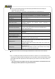
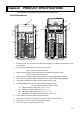
Chapter2 PRODUCT SPECIFICATIONS
This chapter describes product specifications of the SafetyOne.
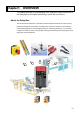
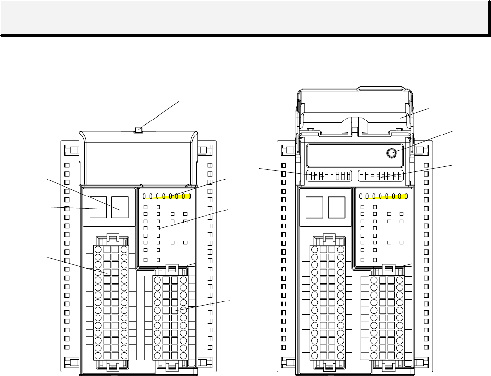
Parts Descriptions
00.1.1 .5.5 11225511553030
TIMERTIMER
SSAFE-INAFE-IN
SSAFE-OUAFE-OU TT
SSTTARAR TT-IN-IN
SOLENOIDSOLENOID
-OU -OUTT
X0X0 X1X1
X2X2 X3X3
X4X4 X5X5
X6X6 X7X7
X1X1 00X1X1 11
X1X1 22X1X1 33
Y0Y0 Y1Y1
Y2Y2 Y3Y3
Y1Y1 77 Y20Y20
X1X1 44X1X1 55
X1X1 66X1X1 77
((SS))
Y1Y1
OUOU TT
Y3Y3
Y5Y5
Y7Y7
Y1Y111
Y1Y133
Y1Y155
Y1Y177
N.CN.C
V-
FEFE
X0X0
X1X1
X2X2
X3X3
X4X4
X5X5
X6X6
X7X7
X1X100
X1X111
X1X122
X1X133
X1X144
X1X155
X1X177
T0T0
T1T1
T2T2
T3T3
T4T4
T5T5
T6T6
T7T7
T1T100
T1T111
T1T122
T1T133
T1T144
T1T155
X1X166
Y0Y0
OUOU TT
ININININ
Y2Y2
Y4Y4
Y6Y6
Y1Y100
Y1Y122
Y1Y144
Y1Y166
Y20Y20
V+
FEFE
LOGICLOGIC ERRORERROR
X0X0
X1X1
X2X2
X3X3
X4X4
X5X5
X6X6
X7X7
X1X100
X1X111
X1X122
X1X133
X1X144
X1X155
X1X177
T0T0
T1T1
T2T2
T3T3
T4T4
T5T5
T6T6
T7T7
T1T100
T1T111
T1T122
T1T133
T1T144
T1T155
X1X166
Y0Y0
OUOU TT
ININININ
Y2Y2
Y4Y4
Y6Y6
Y1Y100
Y1Y122
Y1Y144
Y1Y166
Y20Y20
V+
FEFE
00.1.1 .5.5 11225511553030
TIMERTIMER
SSAFE-INAFE-IN
SSAFE-OUAFE-OU TT
SSTTARAR TT-IN-IN
SOLENOIDSOLENOID
-OU -OUTT
X0X0
X2X2
X4X4
X6X6 X7X7
X1X1 00X1X1 11
X1X1 22X1X1 33
Y0Y0 Y1Y1
Y2Y2 Y3Y3
Y1Y1 77 Y20Y20
X1X1 44X1X1 55
X1X1 66X1X1 77
Y1Y1
OUOU TT
Y3Y3
Y5Y5
Y7Y7
Y1Y111
Y1Y133
Y1Y155
Y1Y177
N.CN.C
V-
FEFE
X1X1
X3X3
X5X5
LOGICLOGIC ERRORERROR
①
②
③
④
⑤ ⑥
⑦
⑧
⑨
⑩
⑪
LOGIC No.
1 2 3 4 5 6 7 8
TIMER
(S)
0 .1 .5 1 2 5 15 30
ENTER
The protective cover is closed The protective cover is open
1. Protective cover: The cover protects unauthorized changing of configuration switches by use of
a locking hole.
2. Input connector: Spring clamp connector for input devices.
(Crimp connector can also be used.)
3. Output connector: Spring clamp connector for output devices and power supply.
(Crimp connector can also be used)
4. Logic LED: The 7-segment green LED indicates the number of logic pattern selected.
5. Error LED: The 7-segment red LED indicates an error in the SafetyOne and peripherals.
6. Timer LED: The eight Timer LEDs indicate the selected timer value.
7. Input/output status LED: The input LEDs indicate the state of inputs.
The output LEDs indicate the state of outputs.
z SAFE-IN: Status of safe inputs, e.g. X0 … X15
z START-IN: Status of start inputs, e.g. X16, 17
z SAFE-OUT: Status of safe outputs, e.g. Y0 … Y3
z SOLENOID-OUT: Status of solenoid outputs, e.g. Y17, 20
8. Logic switch: DIP switch for selecting the internal logic.
9. Timer switch: DIP switch for selecting the OFF-delay time for the safe output.
10. Enter button: button for activation of parameter changes.
11. Lock hole: hole for locking the protective cover