
User Manual

Programming IDEC SmartRelay
IDEC SmartRelay Manual 59
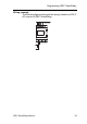
IDEC SmartRelay’s connectors
The term connector refers to all connections and states in
IDEC SmartRelay.
The digital I/O status can be ’0’ or ’1’. Status ’0’ means that
the input does not carry a specific voltage. Status ’1’ means
that the input does carry a specific voltage.
The ’hi’, ’lo’ and ’x’ connectors have been introduced to
make it easier for you to create the circuit program:
’hi’ (high) is assigned the status ’1’,
’lo’ (low) is assigned the status ’0’.
You do not have to use all of the connectors of a block. The
circuit program automatically assigns the unused connectors
a status that ensures proper functioning of the relevant
block. If you prefer to do so, you can identify unused
connectors with an ’x’.
For information on the meaning of the term “block”, refer to
Chapter
3.2.
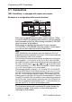
IDEC SmartRelay has the following connectors:
Connectors IDEC SmartRelay base module DM AI
AO
Inputs FL1E-H12RCC/
FL1E-B12RCC,
FL1E-H12RCA/
FL1E-B12RCA
Two groups:
I1... I4 and
I5 ... I8
I9 ...
I24
AI1...
AI8
none
FL1E-H12RCE/
FL1E-B12RCE,
FL1E-H12SND
I1,I2, I3-I6, I7, I8
AI3,AI4 ...AI1,
AI2
I9 ...
I24
AI5...
AI8
Outputs Q1...Q4 Q5 ...
Q16
none AQ1,
AQ2
lo Logical ’0’ signals (off)
hi Logical ’1’ signals (on)
x An existing connection that is not used
DM: Digital module
AI: Analog input module
AO: Analog output module