
User Manual

ML+
L+
M
U1 I2 M2 U2I1 M1
PE
L+M
M
ML+
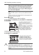
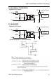
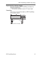
PE terminal for
connecting earth and
shielding the analog
measuring cable
Earth
Cable shielding
DIN rail
PE
RUN/STOP
Current
0...20mA
Reference
Current
Current measurement
Voltage measurement
0-10V
IDEC SmartRelay installation and wiring
IDEC SmartRelay Manual 39
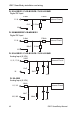
FL1B-J2B2
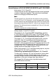
The illustration above shows an example of four–wire
current measurement and two–wire voltage measurement.
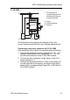
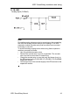
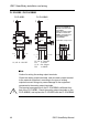
Connecting a two–wire sensor to the FL1B-J2B2
Wire up the two–wire sensor’s connecting wires as follows:
1. Connect the sensor’s output to connection U (0 ... 10 V
vo
ltage measurement) or to connection I (0 ... 20 mA
current measurement) of the FL1B-J2B2 module.
2. Connect the plus connector on the sensor to the 24 V
su
pply voltage (L+).
3. Connect the ground connection of the current output M
(o
n the right side of the sensor, as shown in the figure
above) to the corresponding M input (M1 or M2) on the
FL1B-J2B2 module.