
User Manual

Applications
282 IDEC SmartRelay Manual
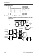
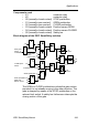
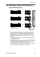
8.4.2 Previous solution
Various control systems are used to operate automatic
gates. The circuit diagram below shows one of these
options.
K1 K5
K3
S1
S0
K3K2
L1
N
K1
H1
K4
S5 p
>
K6
K6
K1
S2
S2 K3
K2 K4
K5
S5 p
>
S1
K3 K1
S4S3
Open
Close
Indicator lamp
Open Close
Auxiliary circuit
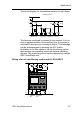
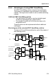
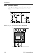
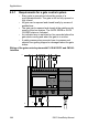
Wiring of a gate control system with FL1E-H12RCC
L1 N I4 I5 I6 I7 I8
Q1 Q2 Q3 Q4
K1 K3
S4S3
L1
N
S1
S2
S0
S5
p
>
S5
p
>
H1
I1 I2 I3
1 2 1 2 1 2 1 2
Open
Close
Indicator lamp