B-1090(6)
Revision History Date Manual No.
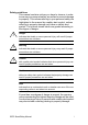
Safety guidelines This manual contains notices you have to observe in order to ensure your personal safety, as well as to prevent damage to property. The notices referring to your personal safety are highlighted in the manual by a safety alert symbol, notices referring to property damage only have no safety alert symbol. The notices shown below are graded according to the degree of danger.
Qualified Personnel The device/system may only be set up and used in conjunction with this documentation. Commissioning and operation of a device/system may only be performed by qualified personnel. Within the context of the safety notices in this documentation qualified persons are defined as persons who are authorized to commission, ground and label devices, systems and circuits in accordance with established safety practices and standards.
Preface Preface Dear customer We thank you for purchasing IDEC SmartRelay and congratulate you on your decision. With IDEC SmartRelay you have acquired a logic module that meets the stringent quality requirements of ISO 9001. IDEC SmartRelay can be used in many fields of applications. Due to its high functionality and easy operation, IDEC SmartRelay offers you the utmost efficiency for almost any application.
Preface Valid range of this manual The manual applies to devices of series FL1E. New features of the FL1E IDEC SmartRelay device series • The Text Display provides an additional display device for messages, and contains four cursor keys and four functions keys that can be used in the circuit program.
Preface Additional differences compared to previous devices (FL1A to FL1D) • Extended set of reference parameters for function blocks. • Enhancements to up/down counter, Operating hours counter, Twelve-month time switch and analog watchdog instruction blocks. • You can find information on compatibility of IDEC SmartRelay FL1E to previous devices at section 2.1.3. Additional support At our Internet address http://smart.idec.
Preface vi IDEC SmartRelay Manual
Contents Preface..................................................................... iii Contents ................................................................. vii 1 Getting started with IDEC SmartRelay................... 1 2 IDEC SmartRelay installation and wiring ............ 17 2.1 Modular IDEC SmartRelay setup ................................................... 20 2.1.1 2.1.2 2.1.3 2.2 2.2.1 2.2.2 2.2.3 2.3 2.3.1 2.3.2 2.3.3 2.3.4 2.3.5 2.4 2.4.1 2.4.2 Maximum setup .........................
3.5 Overview of IDEC SmartRelay menus .......................................... 68 3.6 Writing and starting the circuit program ...................................... 69 3.6.1 3.6.2 3.6.3 3.6.4 3.6.5 3.6.6 3.6.7 3.6.8 3.6.9 3.6.10 3.6.11 3.6.12 3.6.13 3.6.14 3.6.15 Selecting programming mode ....................................................... 69 The first circuit program................................................................. 70 Circuit program input ......................................
4.3.3 4.3.4 4.3.5 4.3.6 4.4 4.4.1 4.4.2 4.4.3 4.4.4 4.4.5 4.4.6 4.4.7 4.4.8 4.4.9 4.4.10 4.4.11 4.4.12 4.4.13 4.4.14 4.4.15 4.4.16 4.4.17 4.4.18 4.4.19 4.4.20 4.4.21 4.4.22 4.4.23 4.4.24 4.4.25 4.4.26 4.4.27 4.4.28 4.4.29 Backup of the real-time clock ...................................................... 123 Retentivity.................................................................................... 123 Parameter protection ...................................................................
4.4.30 4.4.31 Analog math ................................................................................ 225 Analog math error detection ........................................................ 230 5 Configuring IDEC SmartRelay ............................233 5.1 Selecting parameter assignment mode...................................... 234 5.1.1 5.1.2 5.1.3 5.2 5.2.1 5.2.2 5.2.3 5.2.4 5.2.5 Parameters..................................................................................
8.1.4 8.2 8.2.1 8.2.2 8.2.3 8.2.4 8.2.5 8.3 8.3.1 8.3.2 8.4 8.4.1 8.4.2 8.4.3 8.5 8.5.1 8.6 8.6.1 8.6.2 8.6.3 8.7 8.7.1 8.7.2 8.7.3 8.7.4 Special features and expansion options ...................................... 268 Automatic door ............................................................................. 269 Requirements of an automatic door............................................. 269 Conventional solution ..................................................................
A.5 Technical data: FL1B-M08B1S2 ................................................. 307 A.6 Technical data: FL1E-H12RCA/FL1E-B12RCA........................... 309 A.7 Technical data: FL1B-M08D2R2 .................................................. 312 A.8 Technical data: FL1E-H12RCE/ FL1E-B12RCE and FL1B-M08B2R2 ............................................. 314 A.9 Switching capacity and service life of the relay outputs .......... 317 A.10 Technical data: FL1B-J2B2.................................
Getting started with IDEC SmartRelay 1 Here’s IDEC SmartRelay IDEC SmartRelay is a universal logic module made by IDEC that integrates: • Controls • Operator and display panel with background lighting • Power supply • Interface for expansion modules • Interface for a memory cartridge, battery cartridge, combined memory/battery cartridge, IDEC SmartRelay PC cable or USB PC cable • Interface for an optional text display (TD) module • Pre-configured standard functions, for example, on-and off-delays, curre
Getting started with IDEC SmartRelay Which devices are available? IDEC SmartRelay Base is available in two voltage classes: • Class 1 24 V, i.e. 12 V DC, 24 V DC, 24 V AC • Class 2 > 24 V, i.e. 100...
Getting started with IDEC SmartRelay Features of the Text Display The Text Display is available with the FL1E series. It provides an additional display that is wider than the Base module. It has four function keys that you can program in your circuit program as inputs. Like the IDEC SmartRelay Base module, it has four cursor keys, an ESC key and an OK key that you can also program in your circuit program and use for navigation on the Text Display.
Getting started with IDEC SmartRelay It’s your choice The various IDEC SmartRelay Base versions, expansion modules, Text Display and communication modules offer you a highly flexible and adaptive system to suit your specific tasks. The IDEC SmartRelay system offers you many solutions such as for small domestic installations, simple automation tasks, and even complex engineering tasks involving its integration into a bus system (e.g. communication module AS interface).
Getting started with IDEC SmartRelay IDEC SmartRelay Base (e.g.: FL1E-H12RCC) The IDEC SmartRelay structure I1 I2 I3 I4 I5 I6 I7 I8 4 L1 N 1 Q1 2 1 Q2 2 1 Q3 2 90 35 6 1 Q4 2 IDEC SmartRelay expansion module (e.g.: FL1B-M08C2R2) 72 55 35 RUN/STOP 90 4 L1 N I1 I2 I3 I4 1 Q1 2 1 Q2 2 1 Q3 2 1 Q4 2 36 53 1 Power supply 5 Control panel (not for FL1EB12...) 9 Mechanical coding pins 2 Inputs 6 LCD (not for FL1EB12...
Getting started with IDEC SmartRelay 4 IDEC SmartRelay Base (e.g.: FL1E-H12RCE) L+ M I1 I2 I3 I4 I5 I6 I7 I8 4 90 35 6 5 1Q1 2 1 Q2 2 1 Q3 2 1 Q4 2 55 4 L+ M I1 I2 I3 I4 90 RUN/STOP 35 IDEC SmartRelay expansion module (e.g.: FL1B-M08B2R2) 72 1 Q1 2 1 Q2 2 1 Q3 2 1 Q4 2 36 53 1 Power supply 5 Control panel (not for FL1EB12...) 9 Mechanical coding pins 2 Inputs 6 LCD (not for FL1EB12...
Getting started with IDEC SmartRelay FL1B-J2B2 L+ M 90 RUN/STOP 35 4 L+ M PE INPUT2x(0..10V/0..20mA) I1 M1 U1 I2 M2 U2 36 1 Power supply 2 Inputs 9 Mechanical coding pins Mechanical 10 coding sockets 7 RUN/STOP 11 Slide indicator 8 Expansion interface 53 12 PE terminal, for connecting earth and the shielding of analog measuring cables.
Getting started with IDEC SmartRelay FL1D-K2BM2 9 10 1 9 L+M 8 L+M 4 8 11 13 35 RUN/STOP 90 7 12 PE OUTPUT 2x(0..10V or 0/4..
Getting started with IDEC SmartRelay Text Display Communication interface Power supply The Text Display includes a wider display area than the IDEC SmartRelay Display. It includes four programmable cursor keys, four programmable function keys, and an ESC and OK key. You use the included Text Display cable to connect from the communication interface on the right side of the Text Display to the corresponding interface on the left side of the IDEC SmartRelay base module.
Getting started with IDEC SmartRelay Expansion module Digital module FL1B-M Number of Inputs and Outputs B1: 24V DC B2: 12/24V DC C2: 100...240V AC/DC D2: 24V AC/DC S: Tr. (source) output R: Relay output Terminal type 2: non-removable terminal Analog input module FL1B-J Number of Inputs Resolution B: 10bit Terminal type 2: non-removable terminal Analog output module FL1D-K Number of Outputs Resolution B: 10bit blank: 0 ... 10V M: 0 ... 10V, 0/4 ...
Getting started with IDEC SmartRelay Symbols Version with display unit is equipped with 8 inputs and 4 outputs Version without display unit is equipped with 8 inputs and 4 outputs The digital module is equipped with 4 digital inputs and 4 digital outputs The analog module is equipped with 2 analog inputs or two analog outputs, according to the device type The communication module (CM); for example, AS Interface is equipped with 4 virtual inputs and 4 virtual outputs The Text Display IDEC SmartRelay Manua
Getting started with IDEC SmartRelay Versions The following IDEC SmartRelay versions are available: Symbol Designation Supply voltage Inputs Outputs Properties FL1E-H12RCE 12/24 V DC 8 digital (1) 4 relays (10 A) FL1E-H12SND 24 V DC 8 digital (1) 4 solid state no clock 24V / 0.3A FL1E-H12RCA (3) 24 V AC/ 24 V DC 8 digital 4 relays (10A) FL1E-H12RCC (2) 100...
Getting started with IDEC SmartRelay Expansion modules The following expansion modules can be connected to IDEC SmartRelay: Symbol Name Power supply Inputs Outputs FL1B-M08B2R2 12/24 V DC 4 digital 4 relays (5A) FL1B-M08B1S2 24 V DC 4 digital 4 solid state 24V / 0.3A FL1B-M08D2R2 (3) 24 V AC/DC 4 digital 4 relays (5A) (1) 4 relays (5A) FL1B-M08C2R2 100...240 V AC/DC 4 digital FL1B-J2B2 12/24 V DC 2 analog 0 ... 10V or 0 ... 20mA(2) none FL1D-K2B2 24 V DC none 2 analog 0 ...
Getting started with IDEC SmartRelay Certification and approvals IDEC SmartRelay is certified to cULus and FM. • cULus Haz. Loc. Underwriters Laboratories Inc. (UL) to - UL 508 (Industrial Control Equipment) - CSA C22.2 No.
Getting started with IDEC SmartRelay Marine certification requires the surge protective device what manufactured by DEHN+SÖHNE GmbH+Co., in a case of 12/24V DC or 24V DC power line. The required Type No. and Part No.: BVT AD 24, 918 402. See Note on page 298. For further information, see our Internet address (URL: http://www.idec.com/usen) ID for Australia ✔ Our products carrying the label shown at the side are compliant with AS/NZS 2064:1997 (Class A) standard.
Getting started with IDEC SmartRelay 16 IDEC SmartRelay Manual
IDEC SmartRelay installation and wiring 2 General guidelines Please note the following guidelines for installing and wiring your IDEC SmartRelay: • Always ensure that the wiring of your IDEC SmartRelay is compliant with current rules and standards. Also, conform with all national and regional regulations when you install and operate the devices. For information on standards and regulations that apply to your specific case, contact your local authorities.
IDEC SmartRelay installation and wiring What you must note when installing IDEC SmartRelay is designed for fixed and enclosed installation in the housing or the control cabinet. ! Warning Death, serious bodily injury or considerable damage to property can occur. Modules of an IDEC SmartRelay are open facilities. This means that you must install IDEC SmartRelay only in a housing or cabinet.
IDEC SmartRelay installation and wiring These measures are referred to as basic measures. Carrying out tests You must, however, ensure safety in your plant. Before finally commissioning a system, carry out complete functional testing as well as all the necessary safety testing. In testing, also include any predictable faults that can occur. This means that you will avoid any danger to the plant or to people during operation.
IDEC SmartRelay installation and wiring 2.1 Modular IDEC SmartRelay setup 2.1.1 Maximum setup As defined in Chapter 1, IDEC SmartRelay supports a maximum of 24 digital inputs, 8 analog inputs, 16 digital outputs, and 2 analog outputs.
IDEC SmartRelay installation and wiring With any setup, you can plug in an analog output module, which has the maximum of two analog outputs. For FL1E-H12RCE/FL1E-B12RCE and FL1E-H12SND modules, you can configure whether the module uses two or four of the four possible analog inputs. AI inputs are numbered consecutively depending on how many you configure the base module to use. If you configure two inputs, they are numbered AI1 and AI2, and correspond to the I7 and I8 input terminals.
IDEC SmartRelay installation and wiring 2.1.2 Setup with different voltage classes Rules Digital modules can only be directly connected to devices of the same voltage class. You can connect analog and communication modules to devices of any voltage class. Overview: Connecting an expansion module to IDEC SmartRelay base module In the following tables, “X” means that the connection is possible; “-” means that the connection is not possible.
IDEC SmartRelay installation and wiring Overview: Connecting an additional expansion module to an expansion module Expansion module Additional expansion modules FL1BFL1BFL1BFL1BM08B2R2 M08B1S2 M08D2R2 M08C2R2 FL1BJ2B2, FL1DK2B2, FL1DK2BM2 CM FL1B-M08B2R2 x x x - x x FL1B-M08B1S2 x x x - x x FL1B-M08D2R2 x x x - x x FL1B-M08C2R2 - - - x x x FL1B-J2B2, FL1D-K2B2 FL1D-K2BM2 x x x - x x CM AS Interface x x x - x x When setting up expansion modules of different power
IDEC SmartRelay installation and wiring 2.1.3 Compatibility The Text Display module can only be used with equipment series FL1E. You cannot edit message texts from the IDEC SmartRelay base module that contain any of the following parameters: • Par • Time • Date • EnTime • EnDate You can only edit such message texts from WindLGC. When using FL1D-K2B2 and FL1D-K2BM2 with equipment series FL1C or FL1D, the functions are limited to the ones available on this equipment.
IDEC SmartRelay installation and wiring 2.2 Installing/removing IDEC SmartRelay Dimensions The IDEC SmartRelay installation dimensions are compliant with DIN 43880. IDEC SmartRelay can be snap–mounted to 35 mm DIN rails to EN 50022 or on the wall. IDEC SmartRelay width: • Text Display has a width of 128.
IDEC SmartRelay installation and wiring 2.2.1 DIN rail mounting Mounting How to mount an IDEC SmartRelay base module and a digital module onto a DIN rail: IDEC SmartRelay base module: 1. Hook the IDEC SmartRelay base module onto the rail. 2. Push down the lower end to snap it on. The mounting interlock at the rear must engage. 6 1 3 5 2 4 IDEC SmartRelay digital module: 3. On the right side of the IDEC SmartRelay base module/ IDEC SmartRelay expansion module, remove the connector cap. 4.
IDEC SmartRelay installation and wiring 6. Using a screwdriver, push the interlock to the left. In its end position the slide interlock engages in IDEC SmartRelay base module. Repeat steps 3 through 6 to mount further expansion modules. Note The expansion interface on the last expansion module must be covered.
IDEC SmartRelay installation and wiring Removal To remove IDEC SmartRelay: ....... if you have installed only one IDEC SmartRelay base module: Part A 1. Insert a screwdriver into the eyelet at the bottom of the slide interlock and move the latch downward. 2. Swing the IDEC SmartRelay base module off the DIN rail. 1 2 2 4 1 3 A B ....... if you have connected at least one expansion module to IDEC SmartRelay base module: Part B 1. Using a screwdriver, push the integrate slide interlock to the right. 2.
IDEC SmartRelay installation and wiring 2.2.2 Wall-mounting For wall-mounting, first slide the mounting slides on the rear side of the devices towards the outside. You can now wallmount IDEC SmartRelay by means of two mounting slides and two M4 screws (tightening torque 0.8 to 1.2 Nm). Mounting slides Drilling template for wall-mounting Before you can wall-mount IDEC SmartRelay, you need to drill holes using the template shown below. +0.2 35.5–0.0 98 +/– 0.3 +0.2 53.5–0.0 1 2 2 2 +0.2 n x 35.
IDEC SmartRelay installation and wiring 2.2.3 Mounting the Text Display To prepare the mounting surface for the optional Text Display and mount it, follow these steps: 1. Cut a 119.5 mm x 78.5 mm hole in the mounting surface. 78.5+0.5mm 119.5+0.5mm 2. Place the included gasket on the frontplate of the Text Display. 3. Fit the Text Display into the cutout you made in the mounting surface. 4. Attach the mounting brackets (included) to the Text Display. 5.
IDEC SmartRelay installation and wiring Note The number of supplied mounting screws and brackets on the FL1E-RD1 text display depends on the version. The version number of the FL1E-RD1 is found in the lower-right corner on the back of the module. For identifying the version, see page 5. For versions 3 and earlier, 2 screws and brackets are provided. For versions 4 and later, 4 screws and brackets are provided. Listed by UL type 4x / 12 for a tightening torque of 0.2 Nm.
IDEC SmartRelay installation and wiring 2.3 Wiring IDEC SmartRelay Wire IDEC SmartRelay using a screwdriver with a 3-mm blade. You do not need wire ferrules for the terminals. You can use conductors with cross-sections of up to the following thicknesses: • 1 x 2.5 mm2 • 2 x 1.5 mm2 for each second terminal chamber Tightening torque: 0.4...0.5 Nm or 3...4 in-lbs. Recommended ferrules Ferrules order No. For 1-cable connection NIC HIFU Blade Terminals type No. NIC HIFU Insulated Pin Terminals type No.
IDEC SmartRelay installation and wiring 2.3.1 Connecting the power supply IDEC SmartRelays (FL1E-*12RCC, FL1B-M08C2R2) are suitable for nominal line voltages of 100 V AC/DC and 240 V AC/DC. IDEC SmartRelays (FL1E-*12RCA, FL1BM08D2R2) are suitable for a supply voltage of 24 V AC/DC. IDEC SmartRelays (FL1E-H12SND, FL1B-M08B1S2) are suitable for a supply voltage of 24 V DC. IDEC SmartRelays (FL1E-*12RCE, FL1B-M08B2R2) are suitable for a supply voltage of 12 V AC/DC or 24 V AC/DC.
IDEC SmartRelay installation and wiring Circuit protection with AC voltage To suppress voltage peaks on the power supply lines, you can install a metal oxide varistor (MOV). Make sure the operating voltage of the varistor (MOV) used lies at least 20 % above the rated voltage. 2.3.2 Connecting the Text Display power supply The Text Display must be connected to an external power supply that supplies a voltage of 12 V DC or 24 V AC/DC. A power connector is included with the Text Display.
IDEC SmartRelay installation and wiring 2.3.3 Connecting IDEC SmartRelay inputs Requirements At the inputs you connect sensor elements such as: momentary pushbuttons, switches, light barriers, daylight control switches etc. Sensor characteristics for IDEC SmartRelay FL1E-H12RCE/ FL1E-B12RCE I3 ... I6 Signal status 0 < 5 V DC Input current FL1E-H12SND FL1BFL1BM08B2R2 M08B1S2 I1,I2,I7,I8 I3 ... I6 I1,I2,I7,I8 I1 ... I8 I1 ... I8 < 5 V DC < 5 V DC < 5 V DC < 5 V DC < 5 V DC < 0.85 mA < 0.
IDEC SmartRelay installation and wiring Sensor connections Connecting glow lamps and 2-wire proximity switches (Bero) to FL1E-H12RCC/FL1E-B12RCC or FL1BM08C2R2 (AC) The figure below shows how you connect a switch with a glow lamp to IDEC SmartRelay. The current that flows through the glow lamp allows IDEC SmartRelay to detect a “1” signal even though the switch contact is not closed. If, however, you use a switch the glow lamp of which is fitted with a power supply, this response does not occur.
IDEC SmartRelay installation and wiring Special features of FL1E-H12RCE/FL1E-B12RCE and FL1E-H12SND Fast inputs: I3, I4, I5 and I6: These versions are also equipped with fast inputs (up/down counters, frequency triggers). The restrictions mentioned earlier do not apply to these fast inputs.
IDEC SmartRelay installation and wiring When using a potentiometer and 10 V input voltage as the maximum value, you must ensure that with a connected input voltage of 24 V, 14 V must release via the series resistor so that a maximum of 10 V are supplied when you turn the potentiometer one full rotation. With a voltage of 12 V, this can be neglected. Note The FL1B-J2B2 expansion module provides additional analog inputs.
IDEC SmartRelay installation and wiring FL1B-J2B2 L+ M PE L+ M L+ M PE terminal for connecting earth and shielding the analog measuring cable Earth Cable shielding DIN rail RUN/STOP PE M L+ I1 M1 U1 I2 M2 U2 Current Reference 0...20mA Current 0-10V M Current measurement Voltage measurement The illustration above shows an example of four–wire current measurement and two–wire voltage measurement.
IDEC SmartRelay installation and wiring Input Internal Circuit FL1E-H12RCC / FL1E-B12RCC Digital AC/DC Input 390kΩ 180kΩ 270kΩ I1~I8 Internal Circuit 100nF 47kΩ N FL1B-M08C2R2 Digital AC/DC Input 390kΩ 390kΩ 270kΩ I1~I8 Internal Circuit 100nF 62kΩ N When using the AC two-wire sensor AC 2-wire Sensor I1 to I8 R4 N 100 to 240 V AC L1 40 IDEC SmartRelay Manual
IDEC SmartRelay installation and wiring FL1E-H12RCA / FL1E-B12RCA Digital AC/DC Input +5V 4.3kΩ Internal Circuit 150kΩ I1~I8 Internal Circuit 100nF 510Ω 100nF P2 FL1B-M08D2R2 Digital AC/DC Input +5V Internal Circuit 4.
IDEC SmartRelay installation and wiring FL1E-H12RCE / FL1E-B12RCE / FL1E-H12SND Digital DC Input 3.6kΩ 270kΩ I1~I8 Internal Circuit 47nF 2.21kΩ M FL1B-M08B2R2/FL1B-M08B1S2 Digital DC Input 270kΩ 3.6kΩ I1~I8 Internal Circuit 100nF 2.
IDEC SmartRelay installation and wiring FL1B-J2B2 Analog Input (0-20mA) Internal Circuit Note Fluctuating analog values are due to screening on the connecting wire from the analog valuator device to the analog FL1B-J2B2 expansion module (encoder wire) that has either been mounted incorrectly or not at all. To avoid fluctuating analog values when using these expansion modules, proceed as follows: • Use only shielded encoder wires. • Shorten the encoder wire as much as possible.
IDEC SmartRelay installation and wiring 2.3.4 Connecting outputs FL1E-H12RCA / FL1E-B12RCA / FL1E-H12RCC / FL1E-B12RCC / FL1E-H12RCE / FL1E-B12RCE The FL1E-H12RCA / FL1E-B12RCA / FL1E-H12RCC / FL1E-B12RCC / FL1E-H12RCE / FL1E-B12RCE version is equipped with relay outputs. The potential of the relay contacts is isolated from the power supply and the inputs. Requirements for relay outputs You can connect various loads to the outputs, e.g. lamps, fluorescent lamps, motors, contactor relays etc.
IDEC SmartRelay installation and wiring Requirements for transistor outputs The load connected to IDEC SmartRelay must have the following characteristics: • The maximum switched current is 0.3 A per output. Connecting This is how you connect the load to an IDEC SmartRelay with transistor outputs: FL1B-M08 Q5 M Q1 M Q6 M Q2 M Load Load Load: 24 V DC, 0.3 A max.
IDEC SmartRelay installation and wiring FL1D-K2B2 / FL1D-K2BM2 FL1D-K2B2 FL1D-K2BM2 L+ MV1, V2: 0 - 10 V DC R1: >= 5 k I1, I2: 0/4 - 20 mA R2: <= 250 L+ M ① Earth ② DIN rail L+ M L+ M L+M 2 The terminal arrangement on the FL1D-K2BM2 is different from that of the FL1D-K2B2. Check the analog output terminals on the FL1DK2BM2, and replace the FL1D-K2B2 with the FL1D-K2BM2.
IDEC SmartRelay installation and wiring Output Internal Circuit FL1E-H12RCA / FL1E-B12RCA / FL1E-H12RCC / FL1E-B12RCC / FL1E-H12RCE / FL1E-B12RCE / FL1B-M08B2R2 / FL1B-M08C2R2 / FL1B-M08D2R2 Relay Output +24V Internal Circuit Internal Circuit 2 Q1~Q4 47kΩ 1 27kΩ FL1E-H12SND / FL1B-M08B1S2 Transister Output (Source) +24V Internal Circuit Internal Circuit Q1~Q4 10nF 10kΩ M 10nF FL1D-K2B2 / FL1D-K2BM2 Analog Output (0-10V) +24V Internal Circuit Internal Circuit + (V1+, V2+) - 10Ω 100nF 4.
IDEC SmartRelay installation and wiring FL1D-K2BM2 Analog Output (0/4 ...
IDEC SmartRelay installation and wiring 2.3.5 Connecting the AS interface bus To set the address of the module on the AS interface bus, you need an addressing unit. Valid addresses are in the range of 1 to 31. Use each address once only. You can set the address on the AS interface bus before or after installation. If the installed module is addressed via the address socket, the AS-Interface voltage must be disconnected beforehand. This is necessary for safety reasons.
IDEC SmartRelay installation and wiring ! Warning The AS-Interface and IDEC SmartRelay systems must never be connected together electrically! Use safe isolation acc. to IEC 61131-2, EN 50178, UL 508, CSA C22.2 No. 42.
IDEC SmartRelay installation and wiring 2.4 Putting into operation 2.4.1 Switching on the IDEC SmartRelay/Power On IDEC SmartRelay does not have a power switch. The reaction of IDEC SmartRelay during startup depends on the following: • Whether a circuit program is stored in IDEC SmartRelay • Whether a memory cartridge or combined memory/ battery cartridge is inserted • Whether this is an IDEC SmartRelay version without display unit (FL1E-B12...
IDEC SmartRelay installation and wiring Notes for Using Expansion I/O Modules of Version 7 or earlier When using 3 or more expansion I/O modules including those of the versions listed below, immediately after powerup, it takes a specific period of time for the base module to accept input signals from the expansion I/O modules. Until the output terminals on the expansion I/O module are actually turned on or off.
IDEC SmartRelay installation and wiring Before power off After power on or No Program Press ESC No program Press ESC (empty) No program in memory (with program) Mo 09:00 2003-01-27 I: or 0.. 123456789 1..0123456789 2..01234 Q: (empty) 0..123456789 1..0123456 B3: Par = 0300 (with program) Cnt = 0028 IDEC SmartRelay in RUN mode B1 & or Q1 Program in memory (empty) (with program) >Program.. Card.. Setup.. Start Mo 09:00 2002-01-31 I: with stored program from IDEC SmartRelay 0..
IDEC SmartRelay installation and wiring 4. If you have enabled retentivity for at least one function, or a function is permanently retentive, the current values are retained at POWER-OFF. Note When a power failure occurs while you are entering a circuit program, the program in IDEC SmartRelay will be deleted after power is returned. Before you modify the circuit program, save a backup copy of your original to a memory cartridge, a combined memory/battery cartridge or to a computer (WindLGC). 2.4.
IDEC SmartRelay installation and wiring IDEC SmartRelay expansion modules, operating states IDEC SmartRelay expansion modules have three operating states: The LED (RUN/STOP) is lit green, red or orange. LED (RUN/STOP) is lit Green (RUN) Red (STOP) Orange/Yellow The expansion module The expansion module Initialization phase of communicates with the does not communicate the expansion module with the device to its device to the left. left.
IDEC SmartRelay installation and wiring 56 IDEC SmartRelay Manual
Programming IDEC SmartRelay 3 Getting started with IDEC SmartRelay Programming refers to creating a circuit program from the IDEC SmartRelay base module. In this chapter you will learn how to use IDEC SmartRelay to create the IDEC SmartRelay circuit programs for your application. WindLGC is the IDEC SmartRelay programming software that you can use on your PC to quickly and easily create, test, modify save and print the circuit programs.
Programming IDEC SmartRelay 3.1 Connectors IDEC SmartRelay is equipped with inputs and outputs Example of a configuration with several modules: Inputs L+ M AI3 AI4 I3 I4 I5 I6 AI1 AI2 L+ M I9 I10 I11I12 L+ M RUN/STOP L+ M L+ M I13I14I15 I16 RUN/STOP RUN/STOP PE 1 1 Q1 2 1 Q2 2 1 Q3 2 1 Q42 Q5 1Q7 2 Outputs 2 1 Q6 2 INPUT 2x (..10 V/..20 mA) 1 Q8 2 AI5 M3U3AI6M4 U4 1 Q9 1 2 Q11 2 1 2 Q10 1 2 Q12 Analog inputs Each input is identified by the letter I plus a number.
Programming IDEC SmartRelay IDEC SmartRelay’s connectors The term connector refers to all connections and states in IDEC SmartRelay. The digital I/O status can be ’0’ or ’1’. Status ’0’ means that the input does not carry a specific voltage. Status ’1’ means that the input does carry a specific voltage. The ’hi’, ’lo’ and ’x’ connectors have been introduced to make it easier for you to create the circuit program: ’hi’ (high) is assigned the status ’1’, ’lo’ (low) is assigned the status ’0’.
Programming IDEC SmartRelay 3.2 Blocks and block numbers This chapter shows you how to use IDEC SmartRelay elements to create complex circuits and how blocks and I/O are interconnected. In Chapter 3.3 you will learn how to transform a conventional circuit into an IDEC SmartRelay circuit program. Blocks A block in IDEC SmartRelay represents a function that is used to convert input information into output information. Previously you had to wire the individual elements in a control cabinet or terminal box.
Programming IDEC SmartRelay Block representation on the IDEC SmartRelay display The figure below shows a typical view of the IDEC SmartRelay display. As you can see, it can show only one block at a time. We have therefore introduced block numbers to help you check the circuit structure.
Programming IDEC SmartRelay Advantages of block numbers You can connect almost any block to an input of the current block by means of its block number. In this way, you can reuse the interim results of logical or other operations, reduce programming effort, save memory space and clean up your circuit layout. To do so, however, you need to know how IDEC SmartRelay has named the blocks. Note We advise you to create an organizational program chart.
Programming IDEC SmartRelay 3.3 From circuit diagram to IDEC SmartRelay program View of a circuit diagram You know, of course, how a circuit logic is represented in a circuit diagram. Nevertheless, here is an example: S1 S2 Load E1 is switched on and off by means of the switches (S1 OR S2) AND S3. K1 S3 K1 Relay K1 picks up when condition (S1 OR S2) AND S3 is met.
Programming IDEC SmartRelay Note Although you have four inputs available for logic operations (Basic functions, see Chapter 4.2), most of the views will only show three inputs for reasons of clarity. You program this fourth input and assign parameters just like you do with the other three inputs. To create a circuit logic in IDEC SmartRelay, start at the circuit output. The output is the load or relay that is to be switched.
Programming IDEC SmartRelay Wiring example The following figure shows you the wiring, based on a 230 V AC version of IDEC SmartRelay.
Programming IDEC SmartRelay 3.4 The four golden rules for operating IDEC SmartRelay Rule 1 Changing the operating mode • You create the circuit program in programming mode. After power is on, and when the display shows “No Program / Press ESC”, press the ESC key to select programming mode. • Timer and parameter values of an existing circuit program can be edited both in parameter assignment mode and in programming mode.
Programming IDEC SmartRelay Rule 3 Cursor and cursor movement The following applies when you edit a circuit program: • You can move the cursor when it appears in the form of an underscore: - Press , , or to move the cursor in the circuit program. - Press OK to change to ”Select connector/block”. - Press ESC to exit programming mode. • You select a connector/block when the cursor appears as a solid square - Press or to select a connector or a block. - Confirm with OK.
Programming IDEC SmartRelay 3.5 Overview of IDEC SmartRelay menus Programming mode Main Menu >Program.. Card.. Setup.. Start Programming menu OK >Edit.. Clear Prg Password Msg Config ESC OK Transfer menu ESC = IDEC SmartRelay OK > Card Card CopyProtect Setup menu ESC Note: The ‘BM AI NUM’ selection is only available on base modules that support four analog inputs. >Clock LCD Menu Lang BM AI NUM Parameter assignment mode Parameter assignment menu >Stop Set Param Set..
Programming IDEC SmartRelay 3.6 Writing and starting the circuit program After you have designed a circuit, you want to write it to your IDEC SmartRelay. The small example below shows how to do this. 3.6.1 Selecting programming mode You have connected IDEC SmartRelay to the power supply and switched it on. The display now shows you the message: No Program Press ESC Switch IDEC SmartRelay to programming mode by pressing ESC. This will take you to the main menu of IDEC SmartRelay: >Program.. Card..
Programming IDEC SmartRelay Move the ”>” cursor to ”Edit Prg” (for editing the circuit program) and confirm with OK. IDEC SmartRelay now shows you the first output: The first output of IDEC SmartRelay Q1 You are now in programming mode. Press and to select the other outputs. Now start to edit your circuit program. Note Because we have not yet saved a password for the circuit program in IDEC SmartRelay, you can directly enter editing mode.
Programming IDEC SmartRelay Circuit program S1 is connected to the I1 and S2 to the I2 input connector of the OR block. The corresponding layout of the circuit program in IDEC SmartRelay: I1 1 I2 x Q1 Wiring The corresponding wiring: L1 S1 N S2 L1 1 Q1 N 2 I1 I2 1 I3 Q2 2 I4 I5 1 Q3 2 I6 I7 1 I8 Q4 2 L N S1 switches input I1, while S2 switches input I2. The load is connected to the relay Q1.
Programming IDEC SmartRelay 3.6.3 Circuit program input Let us now write the circuit program, starting at the output and working towards the input. IDEC SmartRelay initially shows the output: The first IDEC SmartRelay output Q1 You will see an underscore below the Q in Q1, which is the cursor. The cursor indicates your current position in the circuit program. You can move the cursor by pressing the , , and keys. Now press the key. The cursor moves to the left.
Programming IDEC SmartRelay Now press or until the OR block appears on the display: B1 1 The solid square cursor is still positioned on the block. Q1 Press OK to confirm your entries and exit the dialog. The display now shows: B1 – 1 Q1 Your complete circuit program layout Block number B1 1 Q1 You have now entered the first block. Each new block is automatically assigned a block number. The only thing left to do is interconnect the block inputs. This is how it is done: Press OK.
Programming IDEC SmartRelay Note Press to go the start of the Co list: I1, I2 .... to lo. Press to the end of the Co list: lo, hi, ..... to I1. to go Inputs F1, F2, F3, and F4 are new as of the FL1E device series. They correspond to the four function keys on the optional Text Display. B1 I1 1 Q1 Press OK. I1 is now connected to the input of the OR block. The cursor jumps to the next input of the OR block.
Programming IDEC SmartRelay We do not need the last two inputs of the OR block for this circuit program. You can mark the unused inputs with an ’x’. Enter the ’x’ character twice: 1. Switch to editing mode: Press OK 2. Select the Co list: Press or 3. Accept the Co list: Press OK Press or 4. Select ’x’: 5.
Programming IDEC SmartRelay Next, press ESC. B1 I1 I2 I3 x 1 Q1 Your circuit program layout B1 I1 I2 I3 x 1 Q1 You can review your first circuit program by pressing or to move the cursor through the circuit program. We shall now exit circuit programming mode. This is how it is done: Return to the programming menu: Press ESC Note IDEC SmartRelay has now saved your circuit program to nonvolatile memory. The circuit program remains in the IDEC SmartRelay memory until you explicitly delete it.
Programming IDEC SmartRelay 3.6.4 Assigning a circuit program name You can assign your circuit program a name that consists of up to 16 uppercase/lowercase letters, numbers and special characters. In the programming menu: 1. Move the “>” cursor to ’Edit..’: Press or 2. Accept ’Edit’: Press OK 3. Move the “>” cursor to ’Edit Name’: Press or 4. Accept ’Edit Name’: Press OK Press and to list the alphabet, numbers and special characters, either in ascending or descending order.
Programming IDEC SmartRelay 3.6.5 Password You can protect a circuit program from unauthorized access by assigning it a password. You can only assign or deactivate a password from the IDEC SmartRelay Base module or from WindLGC. You can only change a password from the IDEC SmartRelay Base module.
Programming IDEC SmartRelay uppercase letters for the password, you can quickly access letters “at the end“ of the alphabet (in this example, English) by using the button: Press once to select “Z” Press twice to select “Y”, etc. Let us assign the password “AA” to our first circuit program. The display now shows: Old: No Password New: This procedure is the same as for entering the name of the circuit program. Select “New” and enter: 3. Select “ A”: Press 4. Move to the next letter: Press Press 5.
Programming IDEC SmartRelay Changing the password from the IDEC SmartRelay Base module You must know the current password in order to change it. In the programming menu: 1. Move the ’>’ cursor to ’Password’: Press or 2. Confirm the ’Password’: Press OK Select “Old” and enter your old password (in our case: ’AA’) by repeating steps 3 through 6 as described earlier. The display now shows: Old: AA New: Now you can select “New” to enter the new password, e.g. “ZZ”: 3. Select “Z”: Press 4.
Programming IDEC SmartRelay The display shows: Old: ZZ New: Clear the password by leaving the input box blank: 3. Confirm the “blank” password: Press OK The password is ”cleared”, and you are returned to the programming menu. Note This action disables the password prompt, and thus permits access without a password. Let the password prompt be deactivated for the time being, in order to accelerate progress in our further exercises and examples.
Programming IDEC SmartRelay 1. On the Text Display, press ESC to switch IDEC SmartRelay from RUN mode to STOP mode. Text Display shows the following menu: >Stop Set Param Msg Config Set.. 2. Press OK. The Text Display shows you the following display: Stop Prg >No Yes 3. Press to move the cursor to “Yes”, and press OK. Enter the correct password (in this case: “ZZ”). If you enter an incorrect password, the Text Display returns to the display in Step 1. Password? ZZ 4.
Programming IDEC SmartRelay Note Whenever the Text Display is initialized, the password needs to be inputted again. The next time you start it and access this password-protected function (RUN to STOP), you will be prompted for password entry on the Text Display.
Programming IDEC SmartRelay 3.6.6 Switching IDEC SmartRelay to RUN mode In the main menu, select RUN to start IDEC SmartRelay. 1. Return to the main menu: Press ESC Press or 2. Move the ’>’ cursor to ’Start’: 3. Confirm ’Start’: Press OK IDEC SmartRelay runs the circuit program and shows the following display: Display field of IDEC SmartRelay in RUN mode Mo 09:00 2008-05-26 Press I: 0.. 123456789 1..0123456789 2..01234 Start screen: Date and current time-ofday (only for versions with real-time clock).
Programming IDEC SmartRelay AI: 7: 00000 8: 00000 Analog inputs AI7 to AI8 Press AQ: 1: 00000 2: 01000 Analog outputs AQ1 to AQ2 Press M: Memory Markers M1 to M9 0.. 123456789 1..0123456789 2..01234567 Memory Markers M10 to M19 Memory Markers M20 to M27 Press ESC+C 4 cursor keys for manual intervention in the circuit program (ESC+key) What is meant by: “IDEC SmartRelay is in RUN”? In RUN mode, IDEC SmartRelay executes the circuit program.
Programming IDEC SmartRelay Status indication on the display L1 V4 Let us examine this using our example: =1 L4 V5 L5 I: 0.. 123456789 1..0123456789 2..01234 Q: 0.. 123456789 1..0123456 T4 N 3.6.7 When switch S1 is closed, the status at input I1 is hi. IDEC SmartRelay computes the output states by means of the circuit program. Output Q1 = ‘1’, in this case.
Programming IDEC SmartRelay This is the circuit program layout in IDEC SmartRelay: This is the new block 1 I1 I2 x Q1 x Par You can see the OR block and the output relay Q1 we have already used in the first circuit program. The only difference is the new off-delay block. Editing the circuit program Switch IDEC SmartRelay to programming mode. As a reminder: 1. Switch IDEC SmartRelay to programming mode (in RUN: Press ESC to enter the parameter assignment mode.
Programming IDEC SmartRelay Press to select the SF list: The SF list contains the special function blocks. SF Q1 Press OK. The block of the first special function is shown: Trg Par Q1 When you select a special or basic function block, IDEC SmartRelay shows you the relevant function block. The solid square cursor is positioned on the block. Press or to select the required block.
Programming IDEC SmartRelay Assigning block parameters Now you set the off-delay time T: 1. Move the cursor to Par, if it not already at this position: Press or 2. Switch to editing mode: Press OK IDEC SmartRelay shows the parameters in the parameter assignment window: T: The block parameter B2 is a time function B2 +R T =00:00s Time value Timebase “+” means: The parameter is shown and can be modified in the parameter assignment mode. “R” means: Retentivity is enabled for this block.
Programming IDEC SmartRelay Setting the time Set the time T = 12:00 minutes: 1. Move the cursor to the first digit: 2. Select the digit ’1’: 3. Shift the cursor to the second digit: 4. Select digit ’2’: 5. Move the cursor to the unit: 6. Select the timebase ’m’ (for minutes): Press Press Press Press Press Press or or or or or or Showing/hiding parameters - the parameter protection mode If you want to show/hide the parameter and allow/prevent its modification in parameter assignment mode: 1.
Programming IDEC SmartRelay Note For further information on the protection mode, refer to Chapter 4.3.5. For further information on retentivity, refer to Chapter 4.3.4 You can modify the protection mode and retentivity setting only in programming mode. This is not possible in parameter assignment mode. In this manual, the protection mode (“+” or “--”) and retentivity (“R” or “-/”) settings are only shown in the displays where these can actually be changed.
Programming IDEC SmartRelay 3.6.8 Deleting a block Let us assume you want to delete the block B2 from your circuit program and connect B1 directly to Q1. B1 B2 I1 I2 x x Par Q1 Proceed as follows: 1. Switch IDEC SmartRelay to programming mode (as a reminder, refer to Page 66). 2. Select ’Edit’: Press or 3. Confirm ’Edit’: Press OK (If required, enter your password and confirm with OK.) 4. Select ’Edit Prg’: Press or 5. Confirm ’Edit Prg’: Press OK 6.
Programming IDEC SmartRelay 3.6.9 Deleting block groups Let us assume you want to delete the blocks B1 and B2 from the following circuit program (corresponds with the circuit program in Chapter 3.7.7 ). B1 B2 I1 I2 x x Par Q1 Proceed as follows: 1. Switch IDEC SmartRelay to programming mode (as a reminder, refer to page 66). 2. To select ’Edit’: Press or 3. To confirm ’Edit’: Press OK (If required, enter your password and confirm with OK.) 4. To select ’Edit Prg’: Press or 5.
Programming IDEC SmartRelay 3.6.10 Correcting programming errors Programming errors can be corrected easily in IDEC SmartRelay : • Provided editing mode is not yet closed, you can revert by one step by pressing ESC. • If you have already configured all inputs, simply reconfigure the faulty input: 1. Move the cursor to the faulty position 2. Change to editing mode. Press OK 3. Enter the correct input circuit You can only replace a block with a block that has exactly the same number of inputs.
Programming IDEC SmartRelay Defining a specific analog output value To output a specific analog value at the two analog outputs: Press or 9. Move the ’>’ cursor to ’Defined’: 10.Confirm ’Defined’: Press OK The display shows: AQ1: 00.00 AQ2: 00.00 11.Enter a specific output value for each of the two analog outputs. 12.To confirm your entry: Press OK 3.6.12 Defining the type of analog outputs Analog outputs can be either 0..10V/0..20mA, which is the default, or 4..20mA.
Programming IDEC SmartRelay 3.6.13 Deleting the circuit program and password To delete a circuit program and the password if one is defined: 1. Switch the IDEC SmartRelay to programming mode (main menu). >Program.. Card.. Setup.. Start 2. On the main menu, press ’Program’. Press OK. >Edit.. Clear Prg Password Msg Config IDEC SmartRelay opens the main menu or to move the ’>’ cursor to IDEC SmartRelay changes to the programming menu 3.
Programming IDEC SmartRelay 7. Enter your password. 8. Press OK. The circuit program and the password are deleted. Note In case that you forget the password, you can delete the circuit program and the password using WindLGC. See the onlinehelp for WindLGC for more details. For a base module with versions 3 and earlier, you can delete the circuit program and the password by inputting a wrong password on “Clear Prg” menu three times in a row.
Programming IDEC SmartRelay To enable/disable automatic S/W Time conversion in parameter assignment mode: If you want to enable/disable automatic S/W Time conversion in parameter assignment mode, select in the parameter assignment menu ’Set..’, then menus ’Clock’ and ’S/W Time’. You can now enable/disable automatic S/W Time conversion. Enabling summertime/wintertime conversion You now want to enable this conversion and define or set its parameters: 1. Move the ’>’ cursor to ’On’: Press or 2.
Programming IDEC SmartRelay The table below lists the preset conversions: Start of summertime End of summertime Time zone difference EU Last Sunday in March: 02:00-->03:00 Last Sunday in October: 03:00-->02:00 60 Min. UK Last Sunday in March: 01:00-->02:00 Last Sunday in October: 02:00-->01:00 60 Min. US1 First Sunday in April: 02:00-->03:00 Last Sunday in October: 02:00-->01:00 60 Min. US2 Second Sunday in April: 02:00-->03:00 First Sunday in 60 Min.
Programming IDEC SmartRelay User-defined parameters If none of the parameters/conversions apply to your country, you can customize these under menu item ’. .’. To do so: 1. Confirm ’On’ once again: Press OK 2. Move the ’>’ cursor to ’. .’: Press or 3. Confirm the menu item ’. .
Programming IDEC SmartRelay Note To disable summertime/wintertime conversion in this menu, you merely confirm ‘Off’ with OK. Note Summertime/wintertime conversion only functions when IDEC SmartRelay is operating (in RUN or STOP status). It does not function when IDEC SmartRelay is in buffered operation (see Chapter 4.3.3). 3.6.
Programming IDEC SmartRelay Enabling synchronization You want to enable synchronization: 1. Move the ‘>’ cursor to ‘On’: Press or 2. Confirm ‘On’: Press OK IDEC SmartRelay shows the following display: >On Off Sync: On When synchronization is enabled, IDEC SmartRelay transmits the time-of-day to the expansion modules once daily, after each transition to RUN mode and when the TOD is changed after a ‘Set Clock’ is executed or after a summertime/wintertime conversion.
Programming IDEC SmartRelay 3.7 Memory space and circuit program size The size of a circuit program in IDEC SmartRelay is limited by the memory space (memory used by the blocks). Memory areas • Program memory: IDEC SmartRelay allows only a limited number of blocks in your circuit program. The second limitation is based on the maximum number of bytes a circuit program may contain. The total number of bytes used can be determined by adding up the number of bytes used for the relevant function blocks.
Programming IDEC SmartRelay ! Caution At a power failure, the logical input level may drop to zero before IDEC SmartRelay can save the functions to the retentive memory. In this case, the IDEC SmartRelay saves the function values determined by the zero state at its inputs of the inputs. Example: On-delay With an input (I1) connected to a Trg connector of an On-delay FB as shown in Fig.
Programming IDEC SmartRelay Resources available in IDEC SmartRelay A circuit program in IDEC SmartRelay can occupy the following maximum resources: Bytes Blocks REM 3800 200 250 IDEC SmartRelay monitors memory utilization, and offers only those functions from the lists for which it can actually provide sufficient memory space.
Programming IDEC SmartRelay Program memory Rem memory* Operating hours counter 28 9 Frequency trigger 16 - Analog trigger 16 - Analog differential trigger 16 - Analog comparator 24 - Analog value monitoring 20 - Analog amplifier 12 - Pulse Width Modulator (PWM) 24 - Analog math 20 - Analog math error detection 12 1 Analog multiplexer 20 - Analog ramp control 36 - PI controller 40 2 Function Analog Others Latching relay 8 1 Current impulse relay 12 1 Message t
Programming IDEC SmartRelay Example: Bytes REM 20 Bytes REM – 12 B3 – B2 B1 No 1 No 2 No 3 x Q1 x I2 B4 I1 Par B6 B5 I3 I4 x Par Q2 The sample circuit program contains: Block no.
Programming IDEC SmartRelay Indication of available memory space IDEC SmartRelay shows you the amount of free memory space. Proceed as follows: 1. Switch IDEC SmartRelay to programming mode (as a reminder, refer to page 66). 2. Select ’Edit’: Press or 3. Accept ’Edit’: Press OK 4. Select ’Memory?’: Press or 5.
IDEC SmartRelay functions 4 Organization IDEC SmartRelay provides you with various elements in programming mode, which are organized in the following lists: • Co: Connector list (Connector) (see Chapter 4.1) • GF: List of the basic functions AND, OR, ... (refer to Chapter 4.2) • SF: List of the special functions (refer to Chapter 4.
IDEC SmartRelay functions 4.1 Constants and connectors - Co Constants and connectors (= Co) represent inputs, outputs, memory markers and constant voltage levels (constants). Inputs: 1) Digital inputs Digital inputs are identified with an I. The number of the digital inputs (I1, I2, ...) corresponds to the number of the input connectors of the IDEC SmartRelay base module and of the connected digital modules, in the order of their installation.
IDEC SmartRelay functions There are also 16 blank outputs available. These are identified with an x and cannot be reused in a circuit program (in contrast to memory markers, for example). The list shows all programmed blank outputs, and one blank output which is not yet configured. A blank output, for example, is useful for the special function ”Message texts” (see Chapter 4.4.23), if only the message text is of significance to a circuit program.
IDEC SmartRelay functions Backlight flags M25 and M26 The M25 flag controls the backlight of the IDEC SmartRelay Display. The M26 flag controls the backlight of the Text Display. Note: The backlight lifetime of the Text Display is 20,000 hours. Message text character set flag M27 The M27 flag selects between the two character sets that IDEC SmartRelay uses to display message texts. State 0 corresponds to Character Set 1, and state 1 corresponds to Character Set 2.
IDEC SmartRelay functions Text Display function keys The Text Display has four function keys that you can use in your circuit program. You program these keys in the same way as other inputs. Like the cursor keys, you can press these keys when IDEC SmartRelay is in RUN mode to affect the behavior of the circuit program, and to save switches and inputs. They are identified as F1, F2, F3, and F4. Levels Voltage levels are designated hi and lo.
IDEC SmartRelay functions 4.2 Basic functions list - GF Basic functions represent simple logical elements of Boolean algebra. You can invert the inputs of individual basic functions, that is, the circuit program inverts a logical ”1” at a relevant input to a logical ”0”; if ”0” is set at the input, the program sets a logical ”1”. A programming example is found in Chapter 3.6.3. The GF list contains the basic function blocks you can use for your circuit program.
IDEC SmartRelay functions View in the circuit diagram View in IDEC SmartRelay XOR (exclusive OR) (see page 120) Double changeover contact NOT (negation, inverter) (see page 120) Normally Closed Contact 4.2.1 Name of the basic function AND Circuit diagram of a series circuit with several normally open contacts: Symbol in IDEC SmartRelay: The output of the AND is only 1 if all inputs are 1, i.e. all contacts are closed. At an unused block input (x): x = 1.
IDEC SmartRelay functions 4.2.2 AND with Edge Detection Symbol in IDEC SmartRelay: The output of an edge triggered AND is only 1 if all inputs are 1 and if at least one input was low in the previous cycle. At an unused block input (x): x = 1. Timing diagram for the AND with Edge Detection 1 2 3 4 Q Cycle 4.2.
IDEC SmartRelay functions NAND function logic table 4.2.4 1 2 3 4 Q 0 0 0 0 1 0 0 0 1 1 0 0 1 0 1 0 0 1 1 1 0 1 0 0 1 0 1 0 1 1 0 1 1 0 1 0 1 1 1 1 1 0 0 0 1 1 0 0 1 1 1 0 1 0 1 1 0 1 1 1 1 1 0 0 1 1 1 0 1 1 1 1 1 0 1 1 1 1 1 0 NAND with Edge Detection Symbol in IDEC SmartRelay: The output status of the NAND with Edge Detection is only 1 if at least one input is 0 and if all inputs were 1 in the previous cycle.
IDEC SmartRelay functions Timing diagram for the NAND with Edge Detection 1 2 3 4 Q Cycle 4.2.5 1 2 3 4 5 6 7 8 9 10 OR Circuit diagram of a parallel circuit with several normally open contacts: Symbol in IDEC SmartRelay: The output status of the OR element is only 1 if at least one input is 1, i.e. at least one of the contacts is closed. At an unused block input (x): x = 0.
IDEC SmartRelay functions 4.2.6 NOR (not OR) Circuit diagram of a series circuit with several normally closed contacts: Symbol in IDEC SmartRelay: The output status of the NOR is only 1 if all inputs are 0, i.e. if switched off. The NOR output is set to 0 when one of the inputs is switched on (logical 1 status). At an unused block input (x): x = 0.
IDEC SmartRelay functions 4.2.7 XOR (exclusive OR) The XOR in a circuit diagram, shown as series circuit with 2 changeover contacts: Symbol in IDEC SmartRelay: The output status of the XOR is 1 if the inputs are not equivalent. At an unused block input (x): x = 0. XOR function logic table 1 0 0 1 1 4.2.8 2 0 1 0 1 Q 0 1 1 0 NOT (Negation, Inverter) A normally closed contact in the circuit diagram: Symbol in IDEC SmartRelay: The output status is 1 if the input is 0.
IDEC SmartRelay functions 4.3 Special functions Because of their different input designation, you can see right away that there is a difference between the special functions and basic functions. SFs contain timer functions, retentive functions and various parameter assignment options, which allow you to adapt the circuit program to suit your own requirements. This section provides you with a brief overview of input designations and with some particular background information on SFs.
IDEC SmartRelay functions Connector X at SF inputs SF inputs connected to connector x are set low. That is, the inputs carry a ’lo’ signal. Parameter inputs At some of the inputs you do not apply any signals. You configure the relevant block values instead. Examples: • Par (Parameter): This input will not be connected. Here, you set the relevant block parameters (times, on/off thresholds etc.). • No (Cam): This input will not be connected. Here, you configure the time patterns.
IDEC SmartRelay functions Accuracy of T Because of slight tolerances in the characteristics of electronic components, the set time T may deviate. You can find a detailed description of such deviations in the "Ondelay" topic (Page 131). Accuracy of the timer (Seven-day/Twelve-month time switch) To prevent timing inaccuracy of the real-time clock in C versions caused by this deviation, the timer value is continuously compared with a high-precision timebase and corrected.
IDEC SmartRelay functions resumes operation until the time-to-go has expired, for example. To enable this response, however, the relevant functions must be set retentive. Two options are available: R : The data is retained. / : Current data is not retained (default). See the example on Page 90. SFs operating hours counter, seven-day time switch, twelvemonth time switch and PI controller are always retentive. 4.3.
IDEC SmartRelay functions 4.3.6 Calculating the gain and offset of analog values A sensor is connected to the analog input and converts a process variable into an electrical signal. This value of signal lies within the typical range of this sensor. IDEC SmartRelay always converts the electrical signals at the analog input into digital values from 0 to 1000. A voltage of 0 to 10 V at input AI is transformed internally into a range of values from 0 to 1000.
IDEC SmartRelay functions Mathematical rule Actual value Ax = (internal value at input Ax • gain) + offset Gain and offset calculation The gain and offset is calculated based on the relevant high and low values of the function. Example 1: The available thermocouples have the following technical data: -30 to +70C, 0 to 10 V DC (i.e. 0 to 1000 in IDEC SmartRelay). Actual value = (internal value • gain) + offset, thus -30 = (0 • A) + B, i.e. offset B = -30 +70 = (1000 • A) -30, i.e. gain A = 0.
IDEC SmartRelay functions Example of analog values Process variable -30C 0C +70C 1000 mbar 3700 mbar 5000 mbar Voltage Internal (V) value Gain Offset Value shown (Ax) 0 3 10 0 300 1000 0.1 0.1 0.1 -30 -30 -30 -30 0 70 0 6.75 10 0 675 1000 4 4 4 1000 1000 1000 1000 3700 5000 0 5 10 0 500 1000 0.01 0.01 0.01 0 0 0 0 5 10 0 5 10 0 500 1000 1 1 1 0 0 0 0 500 1000 0 5 10 0 500 1000 10 10 10 0 0 0 0 5000 10000 0 5 10 0 500 1000 0.01 0.01 0.
IDEC SmartRelay functions 4.4 Special functions list - SF When you create your circuit program in IDEC SmartRelay, you find the special function blocks in the SF list. You can invert the inputs of SFs individually, that is, the circuit program converts a logical ”1” at the input into a logical ”0”; a logical ”0” it converts into a logical ”1”. An example of the program code is found in Chapter 3.6.3. The table also specifies whether the relevant function can be set retentive (Rem).
IDEC SmartRelay functions View in IDEC SmartRelay Name of the special function Rem Stairwell Light Switch (see page 146) REM Dual-function switch (see page 148) REM Seven-day time switch (see Page 150) Twelve-month time switch (see Page 155) Counter Up/down counter (see Page 161) REM Operating hours counter REM (see page 164) Fre Frequency trigger (see Page 168) Analog Analog trigger (see page 171) Analog differential trigger (see page 174) Analog comparator (see Page 177) IDEC Smar
IDEC SmartRelay functions View in IDEC SmartRelay Name of the special function Rem Analog value monitoring (see Page 182) Analog amplifier (see Page 185) Analog multiplexer (see Page 210) Pulse Width Modulator (PWM) (see Page 222) Analog math (see Page 225) Analog ramp control (see Page 212) PI controller A/M R PV Par Miscellaneous AQ REM (see Page 216) Latching relay REM (see Page 190) Current impulse relay REM (see Page 191) Message texts P 130 (see Page 193) IDEC SmartRelay Manu
IDEC SmartRelay functions View in IDEC SmartRelay Name of the special function Softkey En Par Q Rem REM (see Page 205) Shift register REM (see Page 208) Analog math error detection (see Page 230) 4.4.1 On-delay Short description The output is only set after a configurable on-delay time has expired. Symbol in IDEC SmartRelay Wiring Input Trg Parameter Output Q IDEC SmartRelay Manual Description A signal at input Trg (Trigger) triggers the on-delay timer.
IDEC SmartRelay functions Parameter T Note the defaults for parameter T in Chapter 4.3.2. The time for parameter T can also be preset based on the actual value of another, already-configured function. You can use the actual values of the following functions: • Analog comparator (actual value Ax - Ay, see Chapter 4.4.18) • Analog trigger (actual value Ax, see Chapter 4.4.16) • Analog amplifier (actual value Ax, see Chapter 4.4.20) • Analog multiplexer (actual value AQ, see Chapter 4.4.
IDEC SmartRelay functions The display in programming mode (example): B12 +R B006 m T If the referenced block (B6, in the example) returns a value that lies out of the valid range, the value is rounded up or down to the next valid value. Parameter preset = Actual value of an already-programmed function How to include the actual value of an already-programmed function: 1. Press to move the cursor to the equal sign of parameter T. B12 +R T =04:10h Press twice B12 +R T =04:10h 2.
IDEC SmartRelay functions The view in parameter assignment mode (example): B12 T =04:10 =04:10h or B12 B006m T Ta =02:00h current time Ta =02:00h Timing diagram The bold section of the timing diagram is also shown in the on-delay icon. Trg Q T T Ta expires Functional description The time Ta is triggered with a 0 to 1 transition at input Trg (Ta is the current IDEC SmartRelay time).
IDEC SmartRelay functions 4.4.2 Off-delay Short description When an on-delay is set, the output is reset when the configured time has expired. Symbol in IDEC SmartRelay Wiring Description Input Trg The off-delay timer starts with a negative edge (1 to 0 transition) at input Trg (Trigger) Input R A signal at input R resets the ondelay time and the output. Parameter The output switches off (transitions from 1 to 0) when the delay time T expires.
IDEC SmartRelay functions Functional description Output Q is set to hi immediately when the input Trg changes to hi. The actual time Ta in IDEC SmartRelay is retriggered at the 1 to 0 transition of Trg. The output remains set. Output Q is reset to 0 with off-delay when Ta reaches the value configured at T (Ta=T). The time Ta is retriggered with a one-shot at input Trg. You can set input R (Reset) to reset the time Ta and the output before Ta has expired.
IDEC SmartRelay functions Parameters TH and TL Note the preset values for the parameters TH and TL in Chapter 4.3.2. The on-delay and off-delay times for parameters TH and TL can be based on the actual value of another, alreadyconfigured function. You can use the actual values of the following functions: • Analog comparator (actual value Ax - Ay, see Chapter 4.4.18) • Analog trigger (actual value Ax, see Chapter 4.4.16) • Analog amplifier (actual value Ax, see Chapter 4.4.
IDEC SmartRelay functions 4.4.4 Retentive on-delay Short description A one-shot at the input triggers a configurable on-delay time. The output is set when this time has expired. Symbol in IDEC SmartRelay Wiring Description Input Trg A signal at input Trg (Trigger) triggers the on-delay timer. Input R A signal at input R resets the ondelay time and the output. Parameter T represents the on-delay time for the output (output status transition 0 to 1).
IDEC SmartRelay functions Functional description The 0 to 1 signal transition at input Trg triggers the current time Ta . Output Q is set when Ta = T. A further signal at input Trg does not influence the time Ta. The output and the time Ta are reset with the next 1 signal at input R. If retentivity is not set, output Q and the expired time are reset after a power failure. 4.4.
IDEC SmartRelay functions Timing diagram The bold section of the timing diagram also appears in the symbol of the wiping relay. Trg Q Ta is expiring T T has not expired Functional description A 0 to 1 transition at input Trg sets the output, and triggers a time Ta during which the output remains set. Output Q is reset to lo (pulse output) when Ta reaches the value preset at T (Ta = T). The output is immediately reset if there is a 1 to 0 transition at input Trg before the specified time has expired.
IDEC SmartRelay functions Parameters TH and TL Note the information on parameter T in Chapter 4.3.2. The pulse width TH and the interpulse width TL can be provided by the actual value of another already-programmed function. You can use the actual values of the following functions: • Analog comparator (actual value Ax - Ay, see Chapter 4.4.18) • Analog trigger (actual value Ax, see Chapter 4.4.16) • Analog amplifier (actual value Ax, see Chapter 4.4.20) • Analog multiplexer (actual value AQ, see Chapter 4.4.
IDEC SmartRelay functions Setting the Par parameter View in programming mode (example): Protection mode and retentivity B25 1+R TL =02:00s TH =03:00s Interpulse width Pulse width Press B25 N =1 2 Number of pulse/pause cycles (example) View in parameter assignment mode (example): B25 TL =02:00s TH =03:00s Ta =01:15s 4.4.7 Current pulse width TL or TH Asynchronous pulse generator Short description The output pulse shape can be modified by reconfiguring the pulse/pause ratio.
IDEC SmartRelay functions Parameters TH and TL Note the information on parameter T in Chapter 4.3.2. The pulse width TH and the interpulse width TL can be provided by the actual value of another already-programmed function. You can use the actual values of the following functions: • Analog comparator (actual value Ax - Ay, see Chapter 4.4.18) • Analog trigger (actual value Ax, see Chapter 4.4.16) • Analog amplifier (actual value Ax, see Chapter 4.4.20) • Analog multiplexer (actual value AQ, see Chapter 4.4.
IDEC SmartRelay functions 4.4.8 Random generator Short description The output of the random generator is set or reset within a configured time. Symbol in IDEC SmartRelay Wiring Description Input En A positive edge ( 0 to 1 transition) at input En (Enable) triggers the ondelay time of the random generator. A negative edge ( 1 to 0 transition) at input En (Enable) triggers the offdelay time of the random generator. Parameter The on-delay is set at random to a value between 0 s and TH.
IDEC SmartRelay functions Timing diagram The bold section of the timing diagram also appears in the symbol of the random generator. En Q T is busy TH TL Functional description The 0 to 1 transition at input En triggers a random on-delay time between 0 s and TH. The output is set when the ondelay time has expired and if the signal at input En remains hi at least for the duration of this time. The time is reset if input En is reset before the on-delay time has expired.
IDEC SmartRelay functions 4.4.9 Stairwell Light Switch Short description An input edge triggers a configurable and retriggerable time. The output is reset after this time has expired. A warning signal can be output before this time has expired to warn of the impending shutdown. Symbol in IDEC SmartRelay Wiring Input Trg Description A signal at input Trg (Trigger) triggers the off-delay time for the stairwell Light Switch.
IDEC SmartRelay functions Timing diagram Trg Q T!L Ta is busy T! T Functional description A 0 to 1 signal transition at input Trg sets output Q. The next 1 to 0 transition at Trg retriggers the current time Ta, and output Q remains set. Output Q is reset when Ta = T. You can output a warning signal before the off-delay time (T - T!) has expired to reset Q for the time of the pre-warning period T!L. A further one-shot at input Trg during Ta retriggers the time Ta .
IDEC SmartRelay functions View in parameter assignment mode (example): B9 1 T =60:00s Current value of T Ta =06:00s 4.4.10 Dual-function switch Short description Switch with two different functions: • Pulse switch with off-delay • Switch (permanent lighting) Symbol in IDEC SmartRelay Wiring Description Input Trg A signal at input Trg (Trigger) sets output Q (permanent light) or resets Q with an off-delay. When active, output Q can be reset with a signal at input Trg.
IDEC SmartRelay functions Parameters T, TL, T! and T!L Note the defaults of the T parameters listed in Chapter 4.3.2. The off-delay time T, the permanent light time TL, the ondelay prewarning time T! and the prewarning time period T!L can be provided by the actual value of another alreadyprogrammed function. You can use the actual values of the following functions: • Analog comparator (actual value Ax - Ay, see Chapter 4.4.18) • Analog trigger (actual value Ax, see Chapter 4.4.
IDEC SmartRelay functions If retentivity is not set, output Q and the expired time are reset after a power failure. Setting the Par parameter Note the defaults specified in Chapter 4.3.2. Note T, T! and T!L must all have the same timebase.
IDEC SmartRelay functions Note Because the FL1E-H12SND does not have a real-time clock, the seven-day time switch function is not available for this version. Symbol in IDEC SmartRelay Wiring Description Cam parameters 1, 2, and 3 At the Cam parameters, you set the on- and off-times of the seven-day time switch for each Cam switch. Here you also configure the days and the time-of-day. Par You specify whether the timer pulses on for one cycle when activated and then reset.
IDEC SmartRelay functions Parameter assignment screen form View of the parameter assignment screen form, for example for Cam1 and the Pulse setting: Block B1 Cam 1 B1 1+ D=MTWTFSS On =06:30 Off=08:00 See Showing/hiding parameters Parameter protection mode on page 90 Weekdays (daily) On-time (06.
IDEC SmartRelay functions Setting the seven-day time switch To set the on-/off-times: 1. Move the cursor to one of the Cam parameters of the timer (e.g. No1). 2. Press OK. IDEC SmartRelay opens the Cam parameter assignment screen form. The cursor is positioned on the weekday. 3. Press and to select one or several days of the week. 4. Press to move the cursor to the first position of the ontime. 5. Set the on-time. Modify the value at the respective position, using the keys and .
IDEC SmartRelay functions Cam1 Cam No1 must set the output of the seven-day time switch daily from 06:30 h to 08:00 h. B1 1+ D=MTWTFSS On =06:30 Off=08:00 Cam2 Cam No2 must set the output of the seven-day time switch every Tuesday from 03:10 h to 04:15 h. B1 2 D=–T––––– On =03:10 Off=04:15 Cam3 Cam No3 must set the output of the seven-day time switch switch every Saturday and Sunday from 16:30 h to 23:10 h.
IDEC SmartRelay functions 4.4.12 Twelve-month time switch Short description The output is controlled by means of a configurable on/off date. You can configure the timer to activate on a yearly, monthly, or user-defined time basis. With any mode, you can also configure the timer to pulse the output during the defined time period.
IDEC SmartRelay functions Example 2: Yearly mode on, Monthly mode off, Pulse on, On Time = 2000–03–15, Off Time = 2099–**–**: Every year on March 15, the timer switches on for one cycle. B6 1+ Yearly = On Monthly=Off Pulse = On B6 2+ ON : YYYY–MM–DD 2000–03–15 B6 3+ OFF : YYYY–MM–DD 2099–**–** Example 3: Yearly mode on, Monthly mode off, Pulse off, On Time = 2008–06–01, Off Time = 2010–08–31: On June 1 of 2008, 2009, and 2010 the timer output switches on and remains on until August 31.
IDEC SmartRelay functions Example 4: Yearly mode on, Monthly mode off, Pulse on, On Time = 2008–03–15, Off Time = 2010–**–**: On March 15 of 2008, 2009, and 2010, the timer output switches on for one cycle. B6 1+ Yearly = On Monthly=Off Pulse = On B6 2+ ON : YYYY–MM–DD 2008–03–15 B6 3+ OFF : YYYY–MM–DD 2010–**–** Example 5: Yearly mode off, Monthly mode off, Pulse off, On Time = 2008–06–01, Off Time = 2008–08–31: On June 1, 2008 the timer output switches on and remains on until August 31, 2010.
IDEC SmartRelay functions Example 6: Yearly mode off, Monthly mode off, Pulse selected, On Time = 2008–03–15, Off Time = ****–**–**: On March 15, 2008 the timer output switches on for one cycle. Because the timer does not have a monthly action or yearly action, the timer output pulses only one time at the specified On Time.
IDEC SmartRelay functions Example 8: Yearly mode on, Monthly mode on, On Time = 2008–**–01, Off Time = 2010–**–05: Starting in 2008, on the first day of each month the timer output switches on and switches off on the fifth day of the month. The timer continues in this pattern through the last month of 2010.
IDEC SmartRelay functions Backup of the real-time clock The internal real-time clock of IDEC SmartRelay is buffered against power failure. The buffering time is influenced by the ambient temperature, and is typically 80 hours at an ambient temperature of 25°C. If you are using the optional IDEC SmartRelay Battery cartridge, or combined IDEC SmartRelay Memory/Battery cartridge, IDEC SmartRelay can retain the clock time for up to two years.
IDEC SmartRelay functions 4.4.13 Up/down counter Short description An input pulse increments or decrements an internal value, depending on the parameter setting. The output is set or reset when a configured threshold is reached. The direction of count can be changed with a signal at input Dir. Symbol in IDEC SmartRelay IDEC SmartRelay Manual Wiring Description Input R A signal at input R resets the internal count value to zero. Input Cnt The function counts the 0 to 1 transitions at input Cnt.
IDEC SmartRelay functions Parameters On and Off The on threshold On and the off threshold Off can be provided by the actual value of another already-programmed function. You can use the actual values of the following functions: • Analog comparator (actual value Ax - Ay, see Chapter 4.4.18) • Analog trigger (actual value Ax, see Chapter 4.4.16) • Analog amplifier (actual value Ax, see Chapter 4.4.20) • Analog multiplexer (actual value AQ, see Chapter 4.4.
IDEC SmartRelay functions Note The system scans the counter limit value cyclically. Thus, if the pulse frequency at the fast inputs I3, I4, I5 or I6 is faster than the cycle time, the special function might not switch until after the specified limit value is exceeded Example: Up to 100 pulses per cycle can be counted; 900 pulses have been counted so far. On = 950; Off = 10000. The output is set in the next cycle, after the value has reached 1000. (The output would not be set at all if the value Off = 980.
IDEC SmartRelay functions 4.4.14 Operating hours counter Short description A configured time is triggered with a signal at the monitoring input. The output is set when this time has expired. Symbol in IDEC SmartRelay Wiring Description Input R A positive edge (0 to 1 transition) at input R resets output Q and sets a configured value MI at the counter for the duration of the time-to-go (MN). Input En En is the monitoring input. IDEC SmartRelay scans the on-time of this input.
IDEC SmartRelay functions Parameter MI The maintenance interval MI can be provided by the actual value of another already-programmed function. You can use the actual values of the following functions: • Analog comparator (actual value Ax - Ay, see Chapter 4.4.18) • Analog trigger (actual value Ax, see Chapter 4.4.16) • Analog amplifier (actual value Ax, see Chapter 4.4.20) • Analog multiplexer (actual value AQ, see Chapter 4.4.26) • Analog ramp control (actual value AQ, see Chapter 4.4.
IDEC SmartRelay functions Functional description The operating hours counter monitors input En. When En = 1, IDEC SmartRelay computes the time expired and the time-to-go MN. IDEC SmartRelay shows these times in parameter assignment mode. Output Q is set when the timeto-go MN = 0. A signal at reset input R resets output Q and sets the preset value of MI at the counter for the duration of MN. The operating hours counter OT is not affected.
IDEC SmartRelay functions Setting the Par parameter View in programming mode: B16 1+R MI = 0100h 00 m B16 1+R MI–> B001h B16 2+R OT =00030h 00 m B16 3+R Q 0:R+En MI is the configurable time interval. The permissible range of values is 0 to 9999 hours. For information on how to assign the actual value of another already-programmed function to a parameter, see section 4.4.
IDEC SmartRelay functions 4.4.15 Frequency trigger Short description The output is set and reset with two configurable frequency triggers. Symbol in IDEC SmartRelay Wiring Input Fre Fre Description The function counts the 0 to 1 transitions at input Fre. 1 to 0 transitions are not counted. Use • inputs I3, I4, I5, I6 for fast counting (only FL1E-H12RCE/FL1EB12RCE and FL1E-H12SND): max. 5 kHz. • any other input or circuit component for counting low frequency signals (typ. 4 Hz).
IDEC SmartRelay functions Timing diagram Q G_T Fre fa = 9 fa = 10 fa = 8 fa = Input frequency fa = 5 On = 9 Off = 5 Functional description The frequency trigger measures the signals at input Fre. The pulses are recorded across a configurable time G_T. Output Q is set and reset in accordance with the set thresholds. See the calculation rule below. Calculation rule • If the On threshold Off threshold, then: Q = 1, if fa > On Q = 0, if fa ≦ Off.
IDEC SmartRelay functions Note The “seconds” timebase is here set as permanent default. When you preset a time G_T of 1 s, IDEC SmartRelay returns the current frequency in parameter fa in Hz. View in parameter assignment mode (example): B15 On =0009 Off =0005 fa =0010 On threshold Off threshold Q = 1 (fa > On) Note fa always represents the total pulses measured per time unit G_T.
IDEC SmartRelay functions 4.4.16 Analog trigger Short description The output is set and reset at two configurable thresholds. Symbol in IDEC SmartRelay * Wiring Description Input Ax You apply the analog signal to be analyzed at input Ax. Use the analog inputs AI1...AI8 (*), the analog memory markers AM1...AM6, the block number of a function with analog output, or the analog outputs AQ1 and AQ2. Parameter A: Gain Range of values: ±10.
IDEC SmartRelay functions Parameter p (number of decimals) Does not apply to the display of On, Off and Ax values in a message text. Does not apply to the comparison of On and Off values! (The compare function ignores the decimal point.) Timing diagram 1000 On Off Ax 0 Q Functional description The function fetches the analog signal at input Ax. Ax is multiplied by the value of the A (gain) parameter, and the value at parameter B (offset) is added to product, i.e.
IDEC SmartRelay functions Setting the Par parameter The gain and offset parameters are used to adapt the sensors to the relevant application. View in programming mode (example): B3 1+ On =+04000 Off =+02000 Parameter protection mode On threshold Off threshold Press B3 2 A =01.00 B =+00000 p =2 Gain Offset Decimals in the message text View in parameter assignment mode (example): B3 On =+04000 Off =+02000 Ax =+05000 On threshold Off threshold Q = 1 (Ax > On) View in the message text (example): +050.
IDEC SmartRelay functions 4.4.17 Analog differential trigger Short description The output is set and reset depending on a configurable threshold and a differential value. Symbol in IDEC SmartRelay Wiring Input Ax Description You apply the analog signal to be analyzed at input Ax. Use the analog inputs AI1...AI8 (*), the analog memory markers AM1...AM6, the block number of a function with analog output, or the analog outputs AQ1 and AQ2. Parameter A: Gain Range of values: 10.
IDEC SmartRelay functions Parameter p (number of decimals) Does not apply to the display of On, Off and Ax values in a message text. Timing diagram A: Function with negative difference O n Off = On + Ax Q Timing diagram B: Function with positive difference Off = On + On Ax Q Functional description The function fetches the analog signal at input Ax. Ax is multiplied by the value of the A (gain) parameter, and the value at parameter B (offset) is added to product, i.e.
IDEC SmartRelay functions Setting the Par parameter The gain and offset parameters are used to adapt the sensors to the relevant application. View in programming mode (example): B3 1+ On =+04000 =–02000 Parameter protection mode On/off threshold Differential value for the on/off threshold Press B3 2 A =01.
IDEC SmartRelay functions 4.4.18 Analog comparator Short description The output is set and reset depending on the difference Ax Ay and on two configurable thresholds. Symbol in IDEC SmartRelay Wiring Inputs Ax and Ay Description You apply the analog signals the difference of which you want to analyze at the inputs Ax and Ay. Use the analog inputs AI1...AI8 (*), the analog memory markers AM1...AM6, the block number of a function with analog output, or the analog outputs AQ1 and AQ2.
IDEC SmartRelay functions Parameter p (number of decimals) Does not apply to Ax, Ay, On, Off and values displayed in a message text. Does not apply to the comparison of on and off values! (The compare function ignores the decimal point.) Timing diagram 1000 Ax 0 1000 Ay 0 1000 Ax - Ay 200 0 Q for Ax - Ay > 200, if On = Off = 200 Functional description The function fetches the analog values from the inputs Ax and Ay.
IDEC SmartRelay functions Setting the Par parameter The gain and offset parameters are used to adapt the sensors to the relevant application. View in programming mode: B3 1+ On =+00000 Off =+00000 Parameter protection mode On threshold Off threshold Press B3 2 A =00.00 B =+00000 p =0 Gain Offset Decimals in the message text Example In a heating control system, the supply Tv and return line temperatures Tr are to be compared, for example with a sensor at AI2.
IDEC SmartRelay functions Configuration (example): B3 1+ On =+00015 Off =+00005 Protection mode On threshold Off threshold Press B3 2 A =00.
IDEC SmartRelay functions Reducing the input response of the analog comparator You can selectively delay the output of an analog comparator by means of the ”On-delay” and ”Off-delay” special functions. With on-delay, output Q is only set if the pulse width of the triggering signal at input Trg (=analog comparator output) is longer than the on-delay time. Using this method, you will obtain a virtual hysteresis and reduce the input response to short signals.
IDEC SmartRelay functions 4.4.19 Analog watchdog Short description This special function saves the process variable of an analog input to memory, and sets the output when the output variable exceeds or drops below this stored value plus a configurable offset.
IDEC SmartRelay functions • Analog comparator (actual value Ax - Ay, see Chapter 4.4.18) • Analog trigger (actual value Ax, see Chapter 4.4.16) • Analog amplifier (actual value Ax, see Chapter 4.4.20) • Analog multiplexer (actual value AQ, see Chapter 4.4.26) • Analog ramp control (actual value AQ, see Chapter 4.4.27) • Analog math (actual value AQ, see Chapter 4.4.30) • PI controller (actual value AQ, see Chapter 4.4.28) • Up/down counter (actual value Cnt, see Chapter 4.4.
IDEC SmartRelay functions Setting the Par parameter The gain and offset parameters are used to adapt the used sensors to the respective application. View in programming mode: B3 1+ 1 = 00000 2 = 00000 Parameter protection mode Differential value for the on/off threshold Press B3 2 A =00.
IDEC SmartRelay functions 4.4.20 Analog amplifier Short description This special function amplifies the value of an analog input and outputs the result at an analog output. Symbol in IDEC SmartRelay Wiring Input Ax x Description You apply the analog signal to be amplified at input Ax. Use the analog inputs AI1...AI8 (*), the analog memory markers AM1...AM6, the block number of a function with analog output, or the analog outputs AQ1 and AQ2. Parameter A: Gain Range of values: 10.
IDEC SmartRelay functions Analog output Analog output can only process values between 0 and 1000. Connect an Analog amplifier in front of the analog output to convert the analog output of the special function within a range between 0 and 1000. The analog output range -5000 to 5000 of a special function is converted to a range between 0 and 1000 in the block diagram below.
IDEC SmartRelay functions • When the type of analog outputs is set to 4-20mA: When internal values less than zero are inputted to the analog output, the analog output module outputs current values less than 4mA. When internal values more than 1000 are inputted to the analog output, the analog output module outputs 20mA.
IDEC SmartRelay functions In the block diagram below, the analog output module operates as the lower part of the timing chart. (example): Analog output value 20mA 4mA -1000 0 1000 Internal value Ax Set each parameter of the functions referring to the table below. Parameters 188 Analog trigger (B006 in the above table) A : Gain = + 1.
IDEC SmartRelay functions Scaling an analog input value You can influence the analog input value of a potentiometer by interconnecting an analog input with an analog amplifier and an analog memory marker. • Scale the analog value at the analog amplifier for further use. • Connect, for example, the time base for parameter T of a time function (e.g. On-/Off-delay, Chapter 4.4.3) or the on and/or off limit specification of an up/down counter (Chapter 4.4.13) to the scaled analog value.
IDEC SmartRelay functions 4.4.21 Latching relay Short description Input S sets output Q, input R resets output Q again. Symbol in IDEC SmartRelay Wiring Description Input S You set output Q with a signal at input S. Input R You reset output Q with a signal at input R. If S and R = 1, the output is reset. Parameter Retentivity: / = No retentivity R = The status is retentive. Output Q Q is set with a signal at input S, and reset with a signal at input R.
IDEC SmartRelay functions 4.4.22 Current impulse relay Short description A short pulse at the input sets and resets the output. Symbol in IDEC SmartRelay Wiring Description Input Trg You set and reset output Q with a signal at input Trg (Trigger). Input S You set output Q with a signal at input S. Input R You reset output Q with a signal at input R. Parameter Selection: RS (R input priority) or SR (S input priority) Retentivity: / = No retentivity R = The status is retentive.
IDEC SmartRelay functions Status diagram Par * * * * * * RS RS SR SR * * * * * * RS RS SR SR Qn-1 0 0 0 0 0 0 0 0 0 0 1 1 1 1 1 1 1 1 1 1 S 0 0 0 0 1 1 1 1 1 1 0 0 0 0 1 1 1 1 1 1 R 0 0 1 1 0 0 1 1 1 1 0 0 1 1 0 0 1 1 1 1 Trg 0 0 – 1 0 0 – 1 0 0 – 1 0 0 – 1 0 0 – 1 0 0 – 1 0 0 – 1 0 0 – 1 0 0 – 1 0 0 – 1 Qn 0 1** 0 0 1 1 0 0 1 1 1 0** 0 0 1 1 0 0 1 1 *: RS or SR **: Triggering signal is effective, because S and R = 0.
IDEC SmartRelay functions Note If Trg = 0 and Par = RS, the special function “Current impulse relay ” corresponds with the special function “Latching relay” (see Chapter 4.4.21). 4.4.23 Message texts Short description With the message text function block, you can configure a message that includes text and other parameters for IDEC SmartRelay to display in RUN mode. You can configure simple message texts from the IDEC SmartRelay Display.
IDEC SmartRelay functions Character Set in IDEC SmartRelay • Common Name Supports Languages Internet Reference ISO8859-1 Latin-1 English, German, Italian, Spanish (partly), Dutch (partly) http://en.wikipedia.org/ wiki/ISO/IEC_8859-1 ISO8859-5 Cyrillic Russian http://en.wikipedia.org/ wiki/ISO/IEC_8859-5 ISO8859-9 Latin-5 Turkish http://en.wikipedia.org/ wiki/ISO/IEC_8859-9 ISO8859-16 Latin-10 French http://en.wikipedia.org/ wiki/ISO/IEC_8859-16 GB-2312 Chinese Chinese http://en.
IDEC SmartRelay functions Chinese Character Set The IDEC SmartRelay base module and Text Display support the Chinese character set (GB-2312) for the People’s Republic of China. The devices use Microsoft Windows encoding for this character set. The Windows encoding allows the devices to display the same characters as shown in the WindLGC message text editor when you are using a Chinese emulator or a Chinese version of Microsoft Windows.
IDEC SmartRelay functions Message Text Function Block Symbol in IDEC SmartRelay 196 Wiring Description Input En A 0 to 1 transition at input En (Enable) starts the output of the message text.
IDEC SmartRelay functions Restriction A maximum of 50 message texts are available. Functional description When IDEC SmartRelay is in RUN mode, IDEC SmartRelay displays the message text that you have configured along with its parameter values upon a 0 to 1 transition of the signal at input En. Based on your setting for the message destination, the message text displays on the IDEC SmartRelay Display, the Text Display, or both.
IDEC SmartRelay functions Example This is how two message texts could be shown: Display field of IDEC SmartRelay in RUN mode Motor 5 STOP AT 10:12 !!Action!! Example: Message text with priority 30 Key Motor 2 3000 hours MAINTENANCE! Example: Message text with priority 10 Press Mo 09:00 2003-01-27 Date and current time-of-day (only for versions with real-time clock). Message Ticking You can configure message text lines to tick or not tick.
IDEC SmartRelay functions Example: Tick Message Character by Character The following illustration shows a one-line, 24-character message text: If you set this message to tick ”character by character” with a tick interval of 0.1 seconds, then the initial appearance of this message line on the IDEC SmartRelay Display or Text Display is as shown in this illustration: After 0.1 second, one character of the message line ticks.
IDEC SmartRelay functions Input P configuration From the input P, you configure the following characteristics of the message text: • Priority • Acknowledgement • Message destination • Tick type, and tick setting for each line To configure the priority and the acknowledgment (programming mode): B33 1+/ Priority 000 Ack=Off “+” means: The parameters and actual values in an active message text can be edited Priority Status of the acknowledgment 1. Increase the priority to 1: 2. Change to ’Ack’: 3.
IDEC SmartRelay functions B33 3+/ TickType Ch by Ch Tick Type: Character by Character (Ch by Ch) or Line by Line (Ln by Ln) 5. If your message text has lines that tick, press to position the cursor on the ”Ch by Ch” line and then press or to select either ”Ch by Ch” or ”Ln by Ln” for the TickType. 6. From the Tick T ype screen, press to enable or disable ticking for each line of the message text.
IDEC SmartRelay functions Parameter or process variable visible in a message text Special function Timers On-delay T, Ta Off-delay T, Ta On-/Off-delay Ta, TH, TL Retentive on-delay T, Ta Interval time-delay relay/ Pulse output T, Ta Edge-triggered interval time-delay relay Ta, TH, TL Asynchronous pulse generator Ta, TH, TL Random generator TH, TL Stairwell Light Switch Ta, T, T!, T!L Dual-function switch Ta, T, TL, T!, T!L Seven-day time switch 3*on/off/day Twelve-month time switch
IDEC SmartRelay functions For timers, a message text can also display the remaining time. “Remaining time” refers to how much time of the parameter setting remains. Bar graphs can be either horizontal or vertical representations of the current or actual value scaled between the minimum and maximum value. For more information on configuring and displaying bar graphs in message texts, refer to the WindLGC online help.
IDEC SmartRelay functions Key input simulation in the active message text You can enable the four cursor keys C , C , C and C in an active message text by pressing ESC plus the relevant cursor key. Setting the Par parameter View in programming mode: .. .. .. .. Parameter assignment screen form for Par Press to select a line for the message text. Press and to select the letter to be displayed in the text. To move the cursor from one position to the other, press and .
IDEC SmartRelay functions 4.4.24 Softkey Short description This special function has the effect of a mechanical pushbutton or switch. Symbol in IDEC SmartRelay En Par Wiring Description Input En Output Q is set with a 0 to 1 transition of the signal at input En (Enable), and if ’Switch=On’ was confirmed in parameter assignment mode. Parameter Programming mode: Selecting the function for pushbutton action for the duration of one cycle, or for switching action.
IDEC SmartRelay functions Functional description In parameter assignment mode, the output is set with a signal at input En, if the ’’Switch’ parameter is set to ’On’ and confirmed with OK. Whether the function was configured for pushbutton or switching action is of no concern here.
IDEC SmartRelay functions 5. To change to the start state: Press or 6. To change the start state: Press or B33 +/ On/Off Start=Off The status is not retentive “Switch” function Q is reset in the init cycle after the program start 7. Confirm your entries with OK View in parameter assignment mode (example): Here, you can set or reset the ’Switch’ parameter (On/Off). When in RUN, IDEC SmartRelay shows the following display: B33 Switch=Off Let us assume you want to set ’Switch’ (On). 1.
IDEC SmartRelay functions 4.4.25 Shift register Short description You can use the shift register function to read the value of an input and to shift its bits left or right. The output value corresponds with the configured shift register bit. The shifting direction can be changed at a special input. Symbol in IDEC SmartRelay Wiring Description Input In Input read at the start of the function. Input Trg A positive edge (0 to 1 transition) at input Trg (Trigger) starts the special function.
IDEC SmartRelay functions Timing diagram In Trg Q Dir S1 S2 S3 S4 S5 S6 S7 S8 0 0 0 0 1 1 0 0 1 0 0 0 0 1 1 0 0 1 0 0 0 0 1 1 1 0 1 0 0 0 0 1 Shift up 1 1 0 1 0 0 0 0 0 1 1 0 1 0 0 0 1 1 0 1 0 0 0 1 S4 = Q (example) Shift down Setting the Par parameter View in programming mode: B3 Q=S8 R Retentivity enabled Preset Press B3 Q=S7 R etc. You can select S8...S1. This special function is not available in parameter assignment mode.
IDEC SmartRelay functions 4.4.26 Analog Multiplexer Short description This special function outputs one of four predefined analog values or 0 at the analog output. Symbol in IDEC SmartRelay Wiring Description Input En A change in status from 0 to 1 at input En (Enable) switches a parameterized analog value to the output AQ, depending on the value of S1 and S2. Inputs S1 and S2 S1 and S2 (selectors) for selecting the analog value to be issued.
IDEC SmartRelay functions Parameter p (number of decimals) Applies only to the values displayed in a message text. Timing diagram En S1 S2 V1 V2 V3 0 V4 AQ Functional description If input En is set, then the function issues one of 4 possible analog values V1 to V4 at the output AQ, depending on the value of S1 and S2. If the input En is not set, then the function issues the analog value 0 at output AQ.
IDEC SmartRelay functions 4.4.27 Analog Ramp Control Short description The Analog ramp control instruction allows the output to be changed from the current level to the selected level at a specified rate. Symbol in IDEC SmartRelay 212 Wiring Description Input En A change in the status from 0 to 1 at input En (Enable) applies the start/ stop level (Offset ”B” + StSp) to the output for 100 ms and starts the ramp operation to the selected level.
IDEC SmartRelay functions Symbol in IDEC SmartRelay IDEC SmartRelay Manual Wiring Description Parameter Level 1 and Level 2: Levels to be reached Range of values for each level: -10,000 to +20,000 MaxL: Maximum value that must not be exceeded under any circumstances. Range of values: -10,000 to +20,000 StSp: Start/Stop offset: value that is added to Offset ”B” to create the start/stop level. If the Start/Stop offset is 0, then the start/stop level is Offset ”B”..
IDEC SmartRelay functions Parameters L1, L2 The analog values for the parameters L1 and L2 can be derived from another already-programmed function. You can use the actual values of the following functions: • Analog comparator (actual value Ax - Ay, see Chapter 4.4.18) • Analog trigger (actual value Ax, see Chapter 4.4.16) • Analog amplifier (actual value Ax, see Chapter 4.4.20) • Analog multiplexer (actual value AQ, see Chapter 4.4.
IDEC SmartRelay functions Functional description If the input En is set, then the function sets the current level to StSp + Offset ”B” for 100 ms. Then, depending on the connection of Sel, the function runs from the level StSp + Offset ”B” to either level 1 or level 2 at the acceleration set in Rate. If the input St is set, the function runs to a level of StSp + Offset ”B” at the acceleration set in Rate. Then the function holds the level at StSp + Offset ”B” for 100 ms.
IDEC SmartRelay functions View in parameter assignment mode: B3 1 L1 =+04000 B020 L2 AQ =00250 Press B3 2 StSp=00222 Rate=00500 Press B3 3+/ A =02.50 B =–00300 Gain Offset 4.4.28 PI controller Short description Proportional-action and integral-action controllers. You can use both types of controller individually or combined. Symbol in IDEC SmartRelay Wiring Input A/M Set the mode of the controller: 1: automatic mode 0: manual mode Input R Use the input R to reset the output AQ.
IDEC SmartRelay functions Symbol in IDEC SmartRelay IDEC SmartRelay Manual Wiring Description Parameter SP: Set-value assignment Range of values: -10,000 to +20,000 KC: Gain Range of values: 00.00 to 99.
IDEC SmartRelay functions Parameters SP and Mq The set-value SP and the value for Mq can be provided by another already-programmed function. You can use the actual values of the following functions: • Analog comparator (actual value Ax - Ay, see Chapter 4.4.18) • Analog trigger (actual value Ax, see Chapter 4.4.16) • Analog amplifier (actual value Ax, see Chapter 4.4.20) • Analog multiplexer (actual value AQ, see Chapter 4.4.26) • Analog ramp control (actual value AQ, see Chapter 4.4.
IDEC SmartRelay functions Timing diagram The nature, manner and speed with which the AQ changes depend on the parameters KC and TI. Thus, the course of AQ in the diagram is merely an example. A control action is continuous; therefore the diagram portrays just an extract. A/M R /– /+ Dir Max SP PV Min Mq Q 500 ms AQ 1. A disturbance causes the PV to drop, as Dir is positioned upwards, AQ increases until PV corresponds again to SP. 2.
IDEC SmartRelay functions Note For further information on the controller basics please refer to the online help for WindLGC. The updated value PV is used to calculate in the formulas: Updated value PV = (PV•gain) + offset • If the updated value PV = SP, then the special function does not change the value of AQ. • Dir = upwards (+) (timing diagram numbers 1. and 3.) - If the updated value PV > SP, then the special function reduces the value of AQ.
IDEC SmartRelay functions Setting the Par parameter View in programming mode (example): B3 SP 1+/ B020 Press B3 2+/ KC =10.00 TI =01:00 Dir=+ Press B3 3+/ B021 Mq Min=–05000 Max=+05000 Press B3 4+/ A =02.50 B =–00300 p =0 View in parameter assignment mode: B3 1 B020 SP PV = 0 AQ =+0250 Press B3 2 KC =10.00 TI =01:00 Dir=+ Press B3 3 B021 Mq Min=–05000 Max=+05000 IDEC SmartRelay Manual Press B3 4 A =02.
IDEC SmartRelay functions 4.4.29 Pulse Width Modulator (PWM) Short description The Pulse Width Modulator (PWM) instruction modulates the analog input value Ax to a pulsed digital output signal. The pulse width is proportional to the analog value Ax. Symbol in IDEC SmartRelay Wiring Description Input Ax Analog signal to be modulated to a pulsed digital output signal. Parameter Min: Range of values: 20,000 Max: Range of values: 20,000 A: Gain Range of values: 10.
IDEC SmartRelay functions Parameters p (number of decimals) Parameter p applies only to the display of the Ax value in a message text Functional description The function reads the value of the signal at the analog input Ax. This value is multiplied by the value of parameter A (gain). Parameter B (offset) is added to the product, as follows: (Ax * Gain) + Offset = Actual value Ax The function block calculates the proportion of the actual value Ax to the range.
IDEC SmartRelay functions 2. An analog value of 300 (range 0...1000) as the value for Ax must be modulated to a digital signal string. The userdefined T (periodic time) parameter is 10 seconds. At the digital output of the PWM function the digital signal string is 3 seconds high, 7 seconds low, 3 seconds high, 7 seconds low and continues in that pattern as long as parameter ”En” = high.
IDEC SmartRelay functions View in parameter assignment mode: B1 1 Min=+00000 Max=+01000 A = 1.00 Press B1 2 B =+00000 T =00:04s 4.4.30 Analog math Short description The analog math block calculates the value AQ of an equation formed from the user-defined operands and operators. Symbol in IDEC SmartRelay Wiring Description Input En A change in the status from 0 to 1 at input En (Enable) enables the analog math function block.
IDEC SmartRelay functions Parameters V1...V4 The analog values for the parameters V1...V4 can be derived from another already-programmed function. You can use the actual values of the following functions: • Analog comparator (actual value Ax - Ay, see Chapter 4.4.18) • Analog trigger (actual value Ax, see Chapter 4.4.16) • Analog amplifier (actual value Ax, see Chapter 4.4.20) • Analog multiplexer (actual value AQ) • Analog ramp control (actual value AQ, see Chapter 4.4.
IDEC SmartRelay functions Functional Description The analog math function combines the four operands and three operators to form an equation. The operator can be any one of the four standard operators: +, -, *, or /. For each operator, you must set a unique priority of High (H), Medium(M), or Low(L). The high operation will be performed first, followed by the medium operation, and then by the low operation. You must have exactly one operation of each priority.
IDEC SmartRelay functions Examples The following tables show some simple example analog math block parameters, and the resulting equations and output values: V1 Op1(Pr1) V2 Op2(Pr2) V3 Op3(Pr3) V4 12 + (M) 6 / (H) 3 - (L) 1 Equation: (12 + (6 / 3)) - 1 Result: 13 V1 Op1(Pr1) V2 Op2(Pr2) V3 Op3(Pr3) V4 2 + (L) 3 * (M) 1 + (H) 4 Equation: 2 + (3 * (1 + 4)) Result: 17 V1 Op1(Pr1) V2 Op2(Pr2) V3 Op3(Pr3) V4 100 - (H) 25 / (L) 2 + (M) 1 Equation: (100 - 25) / (2 + 1)
IDEC SmartRelay functions Setting the Par parameter The following illustration shows the view in programming mode that corresponds to the first example (12 + (6 / 3)) - 1: B1 1+/ V1=+00012 OP1= + PR1=M Press B1 2+/ V2=+0006 OP2=/ PR2=H Press B1 3+/ V3=+00003 OP3=– PR3=L Press B1 4+/ V4=+00001 Qen 0: 0 p =0 Use the and keys to navigate between the operand value, operator, and operation priority. To change a value, use the and keys to scroll through value choices for each value.
IDEC SmartRelay functions 4.4.31 Analog math error detection Short description The analog math error detection block sets an output if an error has occurred in the referenced analog math function block. Symbol in IDEC SmartRelay Wiring Description Input En A change in the status from 0 to 1 at input En (Enable) enables the analog math error detection block. Input R A signal at input R resets the output.
IDEC SmartRelay functions Analog math error detection logic table In the table below, Err represents the parameter of the analog math error detection instruction that selects which type of error to detect. ZD represents the zero division bit set by the analog math instruction at the end of its execution: 1 if the error occurred, 0 if not. OF represents the overflow bit set by the analog math instruction: 1 if the error occurred, 0 if not.
IDEC SmartRelay functions Setting the Par parameter The parameters MathBN, AutoRst, and Err can be set in programming mode or parameter assignment mode. View in programming mode (example): B3 +/ MathBN=B001 AutoRst=N Err=ZD/OF Block number of an alreadyprogrammed analog math instruction Auto Reset (Y or N) ZD, OF, or ZD/OF Use the and keys to navigate between the MathBN, AutoRst, and Err parameters. To change a value, use the and keys to scroll through value choices for each value.
Configuring IDEC SmartRelay 5 Parameter assignment refers to the configuration of the block parameters. You can set delay times for time functions, the switching times of timers, counter threshold values, the monitoring interval of an operating hours counter, the on and off thresholds of the trigger, and more.
Configuring IDEC SmartRelay 5.1 Selecting parameter assignment mode Press ESC to change from RUN to parameter assignment mode: Mo 09:00 2008-05-26 ...Press ESC Note The following applies to earlier device versions up to FL1A: • You open parameter assignment mode by pressing ESC+OK. IDEC SmartRelay changes to parameter assignment mode and opens the parameter assignment menu: >Stop Set Param Set..
Configuring IDEC SmartRelay IDEC SmartRelay shows the main menu of the programming mode: >Program.. Card.. Setup.. Start • Set Param For information on the various parameters, refer to the Chapters 5.1.1 to 5.1.3. • Set.. For information on the various settings, refer to Chapter 5.2. • Prg Name This menu command only allows you to read the name of your circuit program. It is not possible to modify this name in parameter assignment mode (see Chapter 3.6.4). 5.1.
Configuring IDEC SmartRelay 5.1.2 Selecting the parameters To select a parameter: 1. On the parameter assignment menu, select ’Set Param’: Press or Stop >Set Param Set.. Prg Name 2. Confirm with OK. IDEC SmartRelay shows the first parameter. If no parameter can be set, you can press ESC to return to the parameter assignment menu.
Configuring IDEC SmartRelay 5.1.3 Modifying parameters You first select the parameter you want to edit (see Chapter 5.1.2). You change the value of the parameter in the same way as you did in programming mode: 1. Move the cursor to the point at which you want to make the change: Press or 2. To change this value: Press or 3.
Configuring IDEC SmartRelay Current value of a counter View of a counter parameter in parameter assignment mode: B3 On =001234 Off=000000 Cnt=000120 or Current count value B3 On =123456 Off B021 Cnt=000120 You can change the on/off threshold. This does not apply if the on or off threshold represents the result of another function (in the example in section 4.4.13, this is B021 ).
Configuring IDEC SmartRelay 5.2 Setting the default values for IDEC SmartRelay You can set the following default values for an IDEC SmartRelay base module: Clock settings You can set the default values for time-of-day and date, summertime/wintertime conversion and synchronization: • in parameter assignment mode by means of the set menu (“Clock” menu item) • in programming mode by means of the setup menu (“Clock” menu item). Time-of-day and date see Chapter 5.2.1.
Configuring IDEC SmartRelay Start screen settings You can select the default setting for the start screen that displays on IDEC SmartRelay and the Text Display when IDEC SmartRelay transitions to RUN mode: • in parameter assignment mode by means of the set menu (“StartScreen” menu item) See Chapter 5.2.5. Message Text settings You can select settings that apply to all message text function blocks from the Programming menu. See Chapter 4.4.23. 5.2.1 Setting the time of day and date (FL1E-H12RC...
Configuring IDEC SmartRelay IDEC SmartRelay shows the following display. Set Clock Mo 15:30 YYYY-MM-DD 2008-05-26 The cursor is positioned on the weekday. 8. Select the day of the week: Press or 9. Move the cursor to the next position: Press or 10.To change the value: Press or 11.To set the correct TOD, repeat steps 9. and 10. 12.To set the correct date, repeat steps 9. and 10. 13.
Configuring IDEC SmartRelay IDEC SmartRelay shows the following display: Contrast –.... ....+ 8. To change the display contrast: 9. To confirm your entry: Press or Press OK To set the display contrast in programming mode: If you want to set the display contrast in programming mode, select ’Setup’ in the main menu, then menu ’Contrast’. You can now set the display contrast as described earlier (as of step 8.). To set the back light choice in parameter assignment mode: 1.
Configuring IDEC SmartRelay 5.2.3 Setting the menu language The language of the IDEC SmartRelay menus can be one of ten predefined languages: CN (Chinese) DE (German) EN (English) IT (Italian) NL (Dutch) ES (Spanish) FR (French) RU (Russian) TR (Turkish) JP(Japanese) To set the menu language in parameter assignment mode: 1. Select parameter assignment mode (see Chapter 5.1.) 2. On the parameter assignment menu, select ’Set’: Press or 3. Confirm ’Set..’: Press OK 4.
Configuring IDEC SmartRelay 5.2.4 Setting the number of AIs in the base module FL1E-H12RCE/FL1E-B12RCE and FL1E-H12SND support up to four onboard inputs that can be used as either digital or analog inuts (0 ...10V). Inputs I7 (AI1) and I8 (AI2) are available as analog inputs by default, whether you use them or not. Inputs I1 (AI3) and I2 (AI4) are optional analog inputs. IDEC SmartRelay provides a menu where you can choose to use two analog inputs (the default, AI1 and AI2), or four.
Configuring IDEC SmartRelay 5.2.5 Setting the start screen You can select the default setting for the start screen that IDEC SmartRelay and the Text Display will display in RUN mode. You make this selection from the parameter assignment mode by means of the set menu (“StartScreen” menu item). To select the start screen: 1. Select parameter assignment mode (see Chapter 5.1.) 2. On the parameter assignment menu, select ’Set..’: Press or 3. Confirm ’Set..’: Press OK 4. Move to ’StartScreen’: Press or 5.
Configuring IDEC SmartRelay 246 IDEC SmartRelay Manual
IDEC SmartRelay memory and battery cartridge (card) 6 IDEC SmartRelay provides the following cartridges for program storage and real-time clock backup: • IDEC SmartRelay Memory cartridge • IDEC SmartRelay Battery cartridge • IDEC SmartRelay Memory/Battery cartridge Each of the three cartridges is color-coded to make them easily distinguishable from one another. They also vary in size. The IDEC SmartRelay Memory cartridge (purple) provides storage for the circuit program.
IDEC SmartRelay memory and battery cartridge (card) • • Send circuit programs by mail Write and test your circuit program at the office, and then transfer it to an IDEC SmartRelay in the switching cabinet IDEC SmartRelay is supplied with a hood. The IDEC SmartRelay Memory cartridge, IDEC SmartRelay Battery cartridge and IDEC SmartRelay Memory/Battery cartridge are supplied separately.
IDEC SmartRelay memory and battery cartridge (card) Compatibility (Old memory cartridges in newer IDEC SmartRelay modules) ... to earlier versions (FL1C and FL1D devices): Data written to the memory cartridge in the FL1D can be read in all FL1E. But data written to the memory cartridge in the FL1C cannot be read by the FL1E. When the memory cartridge is read by the FL1E, the original data in the FL1E is deleted. Data cannot be written from the FL1E to the memory cartridge. ...
IDEC SmartRelay memory and battery cartridge (card) 6.1 Security function (CopyProtect) The secuirty function provides copy protection for circuit programs on memory cartridges or combined memory/ battery cartridges. Unprotected memory cartridges You can edit circuit programs without restrictions and exchange data between the memory cartridge or combined memory/battery cartridge and the device.
IDEC SmartRelay memory and battery cartridge (card) Assigning a security function To assign a circuit program and copy protection function to the memory cartridge or combined memory/battery cartridge, open the programming mode and select “Card”. 1. Switch IDEC SmartRelay to programming mode (ESC / >Stop). Press or 2. Select the ’Card’ command: 3. To apply ’Card’: Press OK 4. Move the ’>’ cursor to ’CopyProtect’: Press or 5.
IDEC SmartRelay memory and battery cartridge (card) 6.2 Inserting and removing memory and battery cartridges When you remove a memory cartridge or combined memory/battery cartridge that contains a circuit program with copy protection attributes, note the following: The circuit program stored on the cartridge can only be executed if the cartridge remains inserted during system runtime.
IDEC SmartRelay memory and battery cartridge (card) Removing the memory cartridge, battery cartridge or combined memory/battery cartridge To remove the memory cartridge, carefully insert a screwdriver with a 3-mm blade into the groove on the upper end of the card, and lever the module partially out of the slot. You can now remove the memory cartridge. 1. Carefully insert a screwdriver into the slot at the upper end of the memory cartridge, and ease it out of the slot a little. 2.
IDEC SmartRelay memory and battery cartridge (card) 6.3 Copying data from IDEC SmartRelay to the memory cartridge To copy the circuit program to the memory cartridge or combined memory/battery cartridge: 1. Insert the memory cartridge or combined memory/battery cartridge into the slot. 2. Switch IDEC SmartRelay to programming mode (ESC / >Stop). >Program.. Card.. Setup.. Start IDEC SmartRelay main menu 3. The main menu opens. To select the ’Card’ command: Press or 4. Press OK. The transfer menu opens.
IDEC SmartRelay memory and battery cartridge (card) When IDEC SmartRelay has finished copying, it automatically returns you to the main menu: >Program.. Card.. Setup.. Start The circuit program backup is now stored on your memory cartridge or combined memory/battery cartridge and you can remove the cartridge. Do not forget to replace the cap. If power fails while IDEC SmartRelay is copying the circuit program, repeat the process after Power On.
IDEC SmartRelay memory and battery cartridge (card) 6.
IDEC SmartRelay memory and battery cartridge (card) When IDEC SmartRelay has finished copying, it opens the main menu: >Program.. Card.. Setup.. Start Note Before you switch IDEC SmartRelay to RUN, you must ensure that the system you are controlling with IDEC SmartRelay does not represent a source of hazard. 1. Move the ’>’ cursor to ’Start’: 2. Press OK.
IDEC SmartRelay memory and battery cartridge (card) 5. Move the ’>’ cursor to ’Card IDEC SmartRelay’: Press or Card >Card CopyProtect = IDEC SmartRelay 6. Press OK. IDEC SmartRelay copies the circuit program from the memory cartridge or combined memory/battery cartridge to IDEC SmartRelay. (If the memory cartridge is from an incompatible FL1A..FL1B version, IDEC SmartRelay displays this message: “Unknown Card / Press ESC”.
IDEC SmartRelay software 7 WindLGC is available as a programming package for the PC.
IDEC SmartRelay software WindLGC WindLGC runs under Windows 7®, Windows Vista®, Windows 98®, Windows NT 4.0®, Windows Me®, Windows 2000®, Windows XP®. WindLGC is capable of client/server operation and offers you a high degree of freedom and comfort for creating your circuit program. WindLGC V6.2 This is the current version of WindLGC. You will find all the functions and the functionality of the devices described in this manual in the version 6.2.
IDEC SmartRelay software 7.1 Connecting IDEC SmartRelay to a PC Connecting the PC cable To connect IDEC SmartRelay to a PC, you need the IDEC SmartRelay PC cable (Appendix E lists the order number). Turn the power off to the IDEC SmartRelay base module. Remove the cap, memory cartridge, or combined memory/ battery cartridge from your IDEC SmartRelay and connect the cable to this socket. Connect the other end of the cable to the serial port of your PC.
IDEC SmartRelay software Closing the PCIDEC SmartRelay mode When the data transfer is completed, the connection to the PC is shut down automatically. Note If the circuit program created with WindLGC is password protected, both the circuit program and the password are downloaded to IDEC SmartRelay. The password prompt is enabled at the end of the data transfer. The upload of a password protected program created in IDEC SmartRelay is only possible after the correct password is entered in WindLGC.
Applications 8 We have provided a small collection of applications in this manual to give you an impression of the versatility of IDEC SmartRelay. For these examples we have recorded once again the original solution of the circuit diagram, and compared it with the IDEC SmartRelay solutions.
Applications Note IDEC SmartRelay applications are available to all our customers free of charge. The examples provided are noncommittal, serve as general information about the fields of application for IDEC SmartRelay, and may be different to user-specific solutions. The user operates the system at his own responsibility. We refer to the relevant national standards and system-related installation regulations. Although you have four inputs available for logic operations (basic functions, see Chapter 4.
Applications 8.1 Stairway or corridor lighting 8.1.1 Requirements for a stairway lighting system The basic requirements for a stairway lighting system are as follows: • When someone is using the stairway, the lighting should be switched on. • If no-one is in the stairway, the lights should be switched off in order to save energy. 8.1.
Applications Lighting system with current impulse relay Function of a lighting system with current impulse relay : • Press any pushbutton: The lighting is switched on • Press any of the pushbuttons once again: The lighting is switched off. Disadvantage: People often forget to switch off the lights.
Applications Wiring of a lighting system with FL1E-H12RCC Lamps N L PE L1 N I1 I2 I3 I4 I1 I5 I3 I6 I7 I8 Switches Q1 Q2 Q3 Q4 The external wiring of a lighting system with an IDEC SmartRelay is no different than it is for a conventional stairway and corridor lighting system. Only the automatic stairwell light switch/current impulse relay is replaced. Supplementary functions are entered directly in IDEC SmartRelay.
Applications Dual-function switch with IDEC SmartRelay Switch: I1 TH / TL Q1 Lights Output Q1 is set for the duration of a preset time TH with a pulse signal at input I1. The permanent lighting function is enabled by keeping the momentary switch pressed for a specified time TL. 8.1.4 Special features and expansion options Other options for increasing comfort or saving energy are, for example: • A flashing function that indicates that the light is about to be switched off automatically.
Applications 8.2 Automatic door You often find automatic door control systems at the entrance to supermarkets, public buildings, banks, hospitals etc. 8.2.1 Requirements of an automatic door • • • When a person approaches the door, it must open automatically. The door must remain open until the doorway is cleared. When the doorway is cleared, the door must close automatically with a short delay.
Applications 8.2.2 Conventional solution Auxiliary circuit L1 S2 K3 S2 K3 B1 B2 S1 K2 K3 K4 K2 Open Close B1 B2 K1 K1 N K3 K3 K4 Open door Waiting time When someone enters the detection range of one of the motion sensors B1 or B2, the door opening motion is initiated by setting K3. After the detection range of the two motion sensors has been cleared at least for a minimum time, K4 enables the closing motion. 8.2.
Applications Wiring of a door control system with FL1E-H12RCC L1 S1 B1 L1 N 1 Q1 2 K1 I1 I2 I3 I4 1 S2 B2 Q2 2 I5 I6 I7 1 Q3 2 1 I8 Q4 2 K2 N Open Close Components used • K1 • K2 • S1 (normally closed contact) • S2 (normally closed contact) • B1 (normally open contact) • B2 (normally open contact) IDEC SmartRelay Manual contactor relay (open) contactor relay (close) limit switch (close) limit switch (open) infrared motion sensor outside infrared motion sensor inside 271
Applications Door control system with IDEC SmartRelaycircuit diagram 1 I1 I2 x & Q2 RS Open & 1 1 I4 x Q1 I4 T= 4s & Q2 I3 Close 1 Q1 This is what the circuit diagram of the conventional solution looks like. You can simplify this circuit if you make use of the IDEC SmartRelay functions. You can use the off-delay function to replace the latching relay and the on-delay.
Applications 8.2.4 Special features and expansion options Options for increasing comfort and user friendliness are, for example: • You can connect an additional control switch with the positions: Open - Automatic - Closed (O-A-C) • You can connect a buzzer to an output of the IDEC SmartRelay to warn of the closing of the door. • You can enable opening of the door time and direction-dependent, i.e. opening only during business hours, and opening only from the inside after closing time. 8.2.
Applications Block diagram of the extended IDEC SmartRelay solution Cam1: Day= Mo..Fr On = 09:00 Off =18:00 Cam2 : Day= Sa On = 08:00 Off =13:00 Detecting motion x I1 Motion detector B1 Cam1 : Day= Mo..
Applications Detecting motion During business hours, the motion detector B1 initiates the opening of the door when somebody wants to enter the shop. Motion detector B2 initiates the opening of the door when somebody wants to leave the shop. After closing time, the motion detector B2 continues to be used to open the door for 1 hour to allow the customers to leave the shop.
Applications 8.3 Air-conditioning system 8.3.1 Requirements for an air-conditioning system The air-conditioning system supplies fresh air to a room or exhausts the contaminated air from a room. Let us examine following example: Fresh-air fan Flow sensor Flow sensor Exhaust fan • • • • • 276 The room is equipped with an exhaust fan and a fresh-air fan. Both fans are monitored by means of a flow sensor. An excess atmospheric pressure may never develop in the room.
Applications The circuit diagram for conventional solutions is as follows: Auxiliary circuit L1 S0 K1 S1 K2 K5 K4 K5 S2 S2 v> K1 N S3 v> K2 K3 K4 Exhaust air H1 Fresh air K5 Operation H2 Error The fans are monitored by means of flow sensors. If no air flow is registered within a short waiting time, the system is switched off and an error message is output. This message can be acknowledged by pressing the OFF button.
Applications Components used • K1 • K2 • S0 (normally closed contact) • S1 (normally open contact) • S2 (normally open contact) • S3 (normally open contact) • H1 • H2 contactor relay contactor relay STOP pushbutton START pushbutton flow sensor flow sensor signal lamp signal lamp Block diagram of the IDEC SmartRelay solution The block diagram of the air-conditioning system with IDEC SmartRelay : On I1 Error Q3 Q1 Exhaust fan x Off I2 Exhaust fan Q1 Q2 Exhaust fan Exhaust air flow sensor Q1
Applications 8.3.2 Advantages of using IDEC SmartRelay The IDEC SmartRelay solution requires less switchgear. That saves you installation time and space in the control cabinet. You might even be able to use a smaller switching cabinet. Additional IDEC SmartRelay options • The free output (Q4) can be used as isolated signal contact for reporting faults or power failure. • It is possible to switch off of the fans by means of a sequential circuit.
Applications You can also generate a message at output Q4: Q3 Error Q4 Messege The relay contacts of output Q4 are always closed when the system is in operation. Relay Q4 does not drop off unless there is a power failure or a fault in the system. This contact can be used for remote monitoring, for example.
Applications 8.4 Factory door Indicator lamp Safety pressure bar The entrance to a company’s premises is often closed with a gate. The gate is only opened to let vehicles in and out. The gate is controlled by the porter. 8.4.1 Requirements for a gate control system • • • • The gate is opened and closed by means of pushbuttons in the gatehouse. The porter can monitor the operation of the gate at the same time. The gate is normally fully opened or fully closed.
Applications 8.4.2 Previous solution Various control systems are used to operate automatic gates. The circuit diagram below shows one of these options.
Applications Components used • K1 • K2 • S0 (normally closed contact) • S1 (normally open contact) • S2 (normally open contact) • S3 (normally closed contact) • S4 (normally closed contact) • S5 (normally closed contact) contactor relay contactor relay STOP pushbutton OPEN pushbutton CLOSE pushbutton Position sensor OPEN Position sensor CLOSED Safety bar Block diagram of the IDEC SmartRelay solution Q2 Start pushI1 button OPEN Start pushbutton I2 CLOSED T= 5s Q1 Open STOP push- I3 button I4 Gate is
Applications 8.4.3 Extended IDEC SmartRelay solution Our extended control circuit is to open the gate automatically when the safety bar is actuated.
Applications 8.5 Centralized control and monitoring of several factory doors 1 2 1 2 Door II 1 Master Door I 2 Door III 1 Safety bar 2 flashing warning light Often, a company’s premises can be entered at several locations. Not all of the gates can always be monitored locally by personnel. They must therefore be able to be monitored and operated by the porter who sits in a central gatehouse. It must also be possible for a member of staff to open and close the gate locally.
Applications 8.5.1 Requirements for a gate control system • • • • • Every gate is opened and closed by means of a cord-operated switch. The gate is will be fully opened or fully closed. All gate can be opened and closed locally by means of pushbuttons. The gate can be opened and closed at the gatehouse by means of the bus system. The GATE OPEN or GATE CLOSED status is indicated. An indicator lamp is switched on five seconds before the gate starts moving and when the gate is in motion.
Applications Components used • K1 • K2 • S0 (normally open contact) • S1 (normally open contact) • S2 (normally open contact) • S3 (normally open contact) • S4 (normally closed contact) • • contactor relay open contactor relay close cord operated switch open cord operated switch close OPEN pushbutton CLOSE pushbutton position sensor GATE IS OPEN S5 (normally closed contact) position sensor GATE IS CLOSED S6 (normally closed contact) Safety bar Master control system • Q5 • Q6 • I9 • I10 IDEC Smart
Applications Block diagram of the IDEC SmartRelay solution Gate is open Open gate Open gate Open gate Gate is open Open gate by hand Gate is open Close gate by hand Gate is closed Safety bar Gate is closed Close gate Close Closed Safety bar Gate is closed Safety bar Indicator lamp Gate is open Open Close Gate is closed The OPEN GATE and CLOSE GATE pushbuttons initiate the gate motion, provided it is not already moving in the other direction. The gate motion ends at the respective limit switch.
Applications 8.6 Luminous rows Luminous rows 1 Luminous rows 2 Luminous rows 3 Luminous rows 4 Office Corridor When planning lighting systems for commercial locations, the type and number of lamps used is determined by the luminance required. For reasons of cost efficiency, the installation often consists of fluorescent tubes arranged in luminous rows, and are divided into separate switching circuits, according to the way the room is used. 8.6.
Applications 8.6.2 Previous solution L1 lx> K1 B1 E1 K2 S1 S2 K3 K4 K2 S3 S4 K3 K4 K5 K6 K5 K6 E2 E3 E4 E5 E1 K1 K2 N The lamps are switched on and off with current impulse relays, by means of pushbutton control at the door. Regardless of this, they are reset with a timer or daylight control switch signal at the central off input.
Applications 8.6.
Applications Block diagram of the IDEC SmartRelay solution Off pulse triggered with timer Mo..Su 20:00 -- 20.01 Mo..Su 21:00 -- 21.
Applications 8.7 Service water pump The use of rainwater as an addition to the drinking water supply is gaining importance. This saves cost and helps to protect the environment.
Applications 8.7.1 Requirements for a control system of a service water pump • • • 8.7.2 Service water must be available at all times. In case of emergency, the control system must automatically switch over to drinking water supply. When switching over to the drinking water supply, the ingress of rainwater into the drinking water system must be prevented. The service water pump may not be switched on if the reservoir has run low of rainwater (dry-run protection).
Applications 8.7.3 Service water pump system with FL1EH12RCC L1 S1 p< L1 N S2 I1 S3 I2 I3 1 Q1 2 1 Q2 2 K1 Y1 I4 S4 I5 1 Q3 2 I6 I7 I8 1 Q4 2 N Pump Drinking water supply line Apart from the IDEC SmartRelay, all you need is a pressure switch and the float switches to control the pump. If you are using a 3-phase AC motor, you must use a contactor relay to switch the pump.
Applications Block diagram of the IDEC SmartRelay solution Pressure switch I1 x T = 20 s Float switch for dryrun protection OFF I3 Float switch for dryrun protection ON I4 Float switch for drin-king water supply ON Pump Q1 Drinking water supply line Q2 I3 Float switch for drinking water supply OFF 8.7.4 x I2 Special features and expansions The block diagram shows how you can interconnect the pump controls and the solenoid valve. The layout corresponds with the circuit diagram.
A Technical data A.1 General technical data Criterion Tested in accordance with Values IDEC SmartRelay Base Dimensions (WxHxD) Weight Installation 72 x 90 x 55 mm Approx. 190 g on a 35 mm profile rail 4 module widths or wall mounting IDEC SmartRelay expansion modules Dimensions (WxHxD) Weight Installation 36 x 90 x 53 mm Approx. 90 g on a 35 mm profile rail 2 module widths or wall mounting Text Display 128.2 x 86 x 38.7 mm Approx.
Technical data Criterion Tested in accordance with Values Electromagnetic compatibility (EMC) Noise emission EN 55011/A EN 55022/B EN 50081-1 (domestic area) Limit class B group 1 Electrostatic discharge IEC 61000-4-2 Severity 3 8 kV air discharge 6 kV contact discharge Electromagnetic fields IEC 61000-4-3 Field strength 1 V/m and 10 V/m HF currents on cables and cable shielding IEC 61000-4-6 10 V Burst pulses IEC 61000-4-4 Severity 3 2 kV (supply and signal lines) High-energy surge pul
Technical data A.2 Technical data: FL1E-H12RCC/FL1E-B12RCC FL1E-H12RCC FL1E-B12RCC Power supply Input voltage 100...240 V AC/DC Permissible range 85 ... 265 V AC 100 ... 253 V DC Permissible mains frequency 47 ... 63 Hz Power consumption • 100 V AC • 240 V AC • 100 V DC • 240 V DC 25 ... 40 mA 20 ... 30 mA 10 ... 25 mA 6 ... 15 mA Inrush current 0.46 A at 100 V DC 0.46 A at 100 V AC 0.92 A at 240 V DC 0.92 A at 240 VAC Voltage failure buffering • 100 V AC/DC • 240 V AC/DC typ. 10 ms typ.
Technical data FL1E-H12RCC FL1E-B12RCC Input current at • Signal 0 • Signal 1 • Signal 0 • Signal 1 < 0.03 mA AC > 0.08 mA AC < 0.03 mA DC > 0.12 mA DC Delay time at • 0 to 1 : 120 V AC : 240 V AC : 120 V DC : 240 V DC • 1 to 0 : 120 V AC : 240 V AC : 120 V DC : 240 V DC typ. 50 ms typ. 30 ms typ. 25 ms typ. 15 ms typ. 65 ms typ. 105 ms typ. 95 ms typ.
Technical data FL1E-H12RCC FL1E-B12RCC Minimum Switching Load 10 mA, 12 V DC Initial Contact Resistance 100 mmaximum (at 1A, 24V DC) Mechanical Life 10,000,000 operations minimum (no load, 10 Hz) Electrical Life 100,000 operations minimum (rated resistive load, 1800 operations / hour) Switching rate Mechanical 10 Hz Ohmic load/lamp load 2 Hz Inductive load 0.5 Hz Notice: For fluorescent lamps with capacitors, the technical data of fluorescent lamp ballasts must also be considered.
Technical data A.3 Technical data: FL1B-M08C2R2 FL1B-M08C2R2 Power supply Input voltage 100...240 V AC/DC Permissible range 85 ... 265 V AC 100 ... 253 V DC Permissible mains frequency 47 ... 63 Hz Power consumption • 100 V AC • 240 V AC • 100 V DC • 240 V DC 34 ... 45 mA 30 ... 32 mA 5 ... 15 mA 5 ... 10 mA Voltage failure buffering • 100 V AC/DC • 240 V AC/DC typ. 10 ms typ. 20 ms Power loss at • 100 V AC • 240 V AC • 100 V DC • 240 V DC 3.9 ... 4.1 VA 7.4 ... 7.6 VA 0.5 ... 1.8 W 1.2 ... 2.
Technical data FL1B-M08C2R2 Delay time at • 0 to 1 : 120 V AC : 240 V AC : 120 V DC : 240 V DC • 1 to 0 : 120 V AC : 240 V AC : 120 V DC : 240 V DC typ. 50 ms typ. 30 ms typ. 25 ms typ. 15 ms typ. 65 ms typ. 105 ms typ. 95 ms typ.
Technical data FL1B-M08C2R2 Electrical Life 100,000 operations minimum (rated resistive load, 1800 operations / hour) Switching rate Mechanical 10 Hz Ohmic load/lamp load 2 Hz Inductive load 0.5 Hz Notice: For fluorescent lamps with capacitors, the technical data of fluorescent lamp ballasts must also be considered. If the maximum allowed surge current is exceeded, fluorescent lamps must be switched with appropriate contactor relays.
Technical data A.4 Technical data: FL1E-H12SND FL1E-H12SND Power supply Input voltage 24 V DC Permissible range 20.4 ... 28.8 V DC Reverse polarity protection Yes Permissible mains frequency not applicable for this module Power consumption from 24 V DC 40 ... 75 mA 0.3 A per output Inrush current 7.8 A at 24 V DC Voltage failure buffering Power loss at 24 V 1.0 ... 1.
Technical data FL1E-H12SND Line length (shielded and twisted) 10 m Error limit +/- 1.5% at full scale Digital outputs Number 4 Output type Transistor, current-sourcing (1) Electrical isolation No In groups of Yes Output voltage Output current = Supply voltage max. 0.3 A Short circuit-proof and overload-proof Yes Short circuit current limitation Approx.
Technical data A.5 Technical data: FL1B-M08B1S2 FL1B-M08B1S2 Power supply Input voltage 24 V DC Permissible range 20.4 ... 28.8 V DC Reverse polarity protection Yes Permissible mains frequency not applicable for this module Power consumption from 24 V DC 30 ... 45 mA 0.3 A per output Voltage failure buffering Power loss at 24 V 0.8 ... 1.
Technical data FL1B-M08B1S2 Short circuit–proof cos 1 not applicable for this module Short circuit-proof cos 0.5 to 0.7 not applicable for this module Parallel output circuit for power increase Not permitted Protection of output relay (if desired) Switching rate Mechanical Electrical 10 Hz Ohmic load/lamp load 10 Hz Inductive load 0.5 Hz (1): 8 V DC (Version 1 to 4 specifications) (2): 1.0 mA (Version 1 to 4 specifications) (3): 1.
Technical data A.6 Technical data: FL1E-H12RCA/FL1E-B12RCA FL1E-H12RCA FL1E-B12RCA Power supply Input voltage 24 V AC/DC Permissible range 20.4 ... 26.4 V AC 20.4 ... 28.8 V DC Reverse polarity protection not applicable for this module Permissible mains frequency 47 ... 63 Hz Power consumption • 24 V AC • 24 V DC 76 ... 182 mA 40 ... 100 mA Inrush current 2.28 A at 24 V DC 2.48 A at 24 V AC Voltage failure buffering typ. 5 ms Power loss • 24 V AC • 24 V DC 1.8... 4.4 VA 1.0 ... 2.
Technical data FL1E-H12RCA FL1E-B12RCA Digital inputs Number 8, optional P action or N action Electrical isolation No High speed inputs not applicable for this module Input frequency • Normal input • High speed input • max. 4 Hz • not applicable for this module Input voltage • Signal 0 • Signal 1 L < 5 V AC/DC > 12 V AC/DC Input current at • Signal 0 • Signal 1 < 1.0 mA > 2.5 mA Delay time at • 0 to 1 • 1 to 0 typ. 1.5 ms typ.
Technical data FL1E-H12RCA FL1E-B12RCA Fluorescent tubes, uncompensated (25000 switching cycles) 10 x 58 W Derating none; across the entire temperature range Short circuit-proof cos 1 Power protection B16, 600A Short circuit-proof cos 0.5 to 0.7 Power protection B16, 900A Parallel output circuits for power increase Not permitted Protection of output relay (if desired) max.
Technical data A.7 Technical data: FL1B-M08D2R2 FL1B-M08D2R2 Power supply Input voltage 24 V AC/DC Permissible range 20.4 ... 26.4 V AC 20.4 ... 28.8 V DC Reverse polarity protection not applicable for this module Permissible mains frequency 47 ... 63 Hz Power consumption • 24 V AC • 24 V DC 120 ... 146 mA 20 ... 75 mA Voltage failure buffering typ. 5 ms Power loss • 24 V AC • 24 V DC 2.4 ... 4.3 VA 0.4 ... 1.
Technical data FL1B-M08D2R2 Control of a digital input Yes Continuous current Ith max. 5 A per relay Surge current max.
Technical data A.8 Technical data: FL1E-H12RCE/ FL1E-B12RCE and FL1B-M08B2R2 FL1E-H12RCE FL1E-B12RCE FL1B-M08B2R2 Input voltage 12/24 V DC 12/24 V DC Permissible range 10.8 ... 28.8 V DC 10.8 ... 28.8 V DC Reverse polarity protection Yes Yes Inrush current 1.6 A at 12 V DC 7.48 A at 24 V DC Power supply Power consumption • 12 V DC • 24 V DC 60 ... 175 mA 40 ... 100mA 30 ... 140 mA 20 ... 75 mA Voltage failure buffering • 12 V DC • 24 V DC typ. 2 ms typ. 5 ms typ. 2 ms typ.
Technical data FL1E-H12RCE FL1E-B12RCE FL1B-M08B2R2 Delay time at • 0 to 1 • 1 to 0 typ. 1.5 ms <1.0 ms (I3 ... I6) typ. 1.5 ms <1.0 ms (I3 ... I6) typ. 1.5 ms Line length (unshielded) 100 m 100 m typ. 1.5 ms Analog inputs Number 4 (I1=AI3, I2=AI4, I7=AI1, I8=AI2) Range 0 ... 10 V DC input impedance 72 k Cycle time for analog value generation 300 ms max. Input voltage 28.8 V DC Line length (shielded and twisted) 10 m Error limit +/- 1.
Technical data FL1E-H12RCE FL1E-B12RCE FL1B-M08B2R2 Short circuit-proof cos 0.5 to 0.7 Power protection B16, 900A Power protection B16, 900A Parallel output circuits for power increase Not permitted Not permitted Protection of output relay (if desired) max. 16 A, characteristic B16 max.
Technical data A.9 Switching capacity and service life of the relay outputs Switching capacity and service life of the contacts with ohmic load (heating): Switching cycles/million 12/24 V AC/DC 100/110 V AC 230/240 V AC 120 V DC 240 V DC 0.5 0.4 0.3 Maximum 10 A Maximum 10 A Maximum 10 A Maximum 0.2 A Maximum 0.1 A 0.2 0.
Technical data A.10 Technical data: FL1B-J2B2 FL1B-J2B2 Power supply Input voltage 12/24 V DC Permissible range 10.8 ... 28.8 V DC Power consumption 25 ... 50 mA Voltage failure buffering typ. 5 ms Power loss at • 12 V • 24 V 0.3 ... 0.6 W 0.6 ... 1.2 W Electrical isolation No Reverse polarity protection Yes Ground terminal for connecting ground and shielding of the analog measuring line Analog inputs Number 2 Type Unipolar Input range 0 ... 10 V DC (input impedance 76 k) or 0 ...
Technical data A.11 Technical data: FL1D-K2B2, FL1D-K2BM2 FL1D-K2B2 FL1D-K2BM2 Power supply Input voltage 24 V DC 24 V DC Permissible range 20.4 ... 28.8 V DC 20.4 ... 28.8 V DC Power consumption 25 ...50 mA 35 ...90 mA Voltage failure buffering typ. 5 ms typ. 5 ms Power loss at 24 V 0.6 ... 1.2 W 0.9 ... 2.2 W Electrical isolation No No Reverse polarity protection Yes Yes Ground terminal for connecting ground and shielding of the analog output line.
Technical data A.12 Technical data: Text Display Text Display Mechanical data Dimensions (WxHxD) Weight Installation 128.2 x 86 x 38.7 mm Approx. 220 g Bracket mounting Keyboard Display Membrane keypad with 10 keys FSTN-Graphic Display with 128 x 64 (columns x rows), LED backlight Power supply Input voltage 24 V AC/DC 12 V DC Permissible range 20.4 ... 26.4 V AC 10.2 ... 28.8 V DC Permissible mains frequency 47 ... 63 Hz Power consumption • 12 V DC • 24 V DC • 24 V AC typ. 65 mA typ.
Determining the cycle time B The program cycle is the complete execution of the circuit program, that is, primarily the reading in of the inputs, the processing of the circuit program and the subsequent reading out of the outputs. The cycle time is the time required to execute a circuit program once in full. The time required for a program cycle can be determined using a short test program.
Determining the cycle time Test program 1. Create the test program by linking an output to a frequency trigger and connecting the trigger input with an inverted marker. B1 Output Qx or other marker Mx M1 Qx Par B2 1 M1 M1 2. Configure the frequency trigger as shown below. A pulse is generated in each program cycle due to the inverted marker. The trigger interval is set to 2 seconds. B1 1+ On =1000 Off=0000 Press B1 2 G_T=02:00s 3.
Determining the cycle time Explanation The inverted marker block changes its output signal at each program execution. Thus, one logic level (high or low) width is exactly equivalent to the length of one cycle. Hence, a period lasts 2 cycles. The frequency trigger indicates the ratio of periods per 2 seconds, which results in the ratio of cycles per second.
Determining the cycle time 324 IDEC SmartRelay Manual
IDEC SmartRelay without display C Because some specific applications do not require operator control and monitoring units such as buttons or a display, we provide the FL1E-B12RCE, FL1E-B12RCA and FL1EB12RCC versions without display.
IDEC SmartRelay without display Operating characteristics IDEC SmartRelay is ready for operation when power is switched on. Switching off an IDEC SmartRelay without display is equivalent to disconnecting the power supply, e.g. as if you were removing the plug. The circuit program of FL1E-B12... versions cannot be started or stopped by means of buttons. This is why the FL1E-B12...
IDEC SmartRelay without display Reading current data WindLGC (see Chapter 7) provides an online test for reading the current data of all functions while the system is in RUN. If your IDEC SmartRelay without display holds a protected memory cartridge or combined memory/battery cartridge, you cannot read the current data unless you enter the correct password for the circuit program.
IDEC SmartRelay without display 328 IDEC SmartRelay Manual
IDEC SmartRelay menu structure D.1 IDEC SmartRelay base module D Menu overview >Program Card Setup Start No Program Circuit program is busy (RUN) Mo 09:00 2008-05-26 See “Start menu“ No Program Press ESC See “Main menu” >Stop Set Param Set Prg Name >Yes Parameter setting (Chapter 5.1.1 cont.) Default values setting (Chapter 5.2 cont.) Display of the program name Parameter assignment menu Main menu (ESC / >Stop) >Stop/>Yes >Program Card Setup Start >Edit..
IDEC SmartRelay menu structure Transfer menu (ESC / >Stop >Card) > –>Card Copying the circuit program from IDEC SmartRelay to the memory cartridge or combined memory/battery cartridge (Chapter 6.3) >Card–> Copying the program from the memory cartridge or combined memory/battery cartridge to IDEC SmartRelay (Chapter 6.4) >CopyProtect Setting the program/copy protection (Chapter 6.1) Setup menu (ESC / >Stop >Clock.. >LCD >Setup) >Set Clock Setting the time/date (Chapter 5.2.
IDEC SmartRelay menu structure D.2 Text Display Menu overview >Setup Msg Config Start No Program Circuit program is busy (RUN) Mo 09:00 2008-05-26 No Program Press ESC See “Main menu” >Stop Set Param Msg Config Set .. >Yes Parameter setting (Chapter 5.1.1 cont.) Message text global settings (See Main menu and section 4.4.23) Default values setting (Chapter 5.2 cont.
IDEC SmartRelay menu structure Start Menu (base module in RUN) Everything clear? SmartRelay Mo 09:00 2008–05–26 max. 50 message texts I: Q: AI: 0.. 123456789 0.. 123456789 1: 00000 1..0123456789 1..0123456 2: 01000 2..01234 Date/time 3: 00253 Inputs Outputs AI: AI: AQ: M: 4: 00010 7: 00000 1: 00000 0.. 123456789 5: 00000 8: 00000 2: 01000 1..0123456789 6: 00005 Analog inputs ESC+C 2..
E Type Numbers Table A IDEC SmartRelay Modules Name Type Number Rated Input Input Output Output Display Real and Time Power Type Type Type Type Voltage (Digital) (Analog) (Relay) (Analog) Keypad Clock Base Module (IDEC SmartRelay Base or Pure) FL1E-H12RCC 100240V AC/DC FL1E-B12RCC FL1E-H12RCA 24V AC/ DC FL1E-B12RCA FL1E-H12RCE FL1E-B12RCE Yes 8 - 4 - 8 - 4 - 4 - 4 12/24V 8 (I1, I2, DC (I1-I8) I7, I8) FL1E-H12SND 24V DC Yes - Yes Yes Yes 4 8 (I1, I2, 4 (Tr) (I1-I8) I7, I8) - Ye
Type Numbers Cable and Accessories Table B Name WindLGC Function Type Number Exclusive Programming Software for IDEC SmartRelay (incl.
Index Index A AIs in Base Module 244 AM See Analog module Amplifier analog 185 Analog comparator 177 values 125 Analog amplifier 185 Analog differential trigger 174 Analog math 225 Analog math error detection 230 Analog module 2, 11 Analog multiplexer 210 Analog output type 95 Analog output values 94 Analog outputs 46, 186 Analog ramp control 212 Analog trigger 171 Analog value monitoring 182 Analog watchdog 182 AND 115 Applications 263 AQ in Stop 94 AQ type 95 AS interface 3 AS interface bus communication
Index assigning 77 Circuit program size 103 Circuit programs archiving 247 reproduce 247 send by mail 248 Closing the programming mode 91 CM See Communications module Co 109, 110 Combined memory/battery cartridge 247 Communication module AS interface 3 Communication modules 3 Communications module AS interface 11 Compatibility Versions 249 Connecting AS interface bus 49 Inputs 35 outputs 44 Connector 26 Connectors 58, 110 hi 59 IDEC SmartRelay 59 inputs 59 lo 59 open 113 outputs 59 unused 59, 64 x 59, 64, 1
Index Factory door 281 factory door controlling 285 monitoring 285 lighting corridor 265 stairway 265 Luminous rows 289 Service water pump 293 exclusive OR 120 Expansion modules 2, 58 Analog 2 analog 59 digital 2, 59 operating state 55 F Flag blocks 111 FM 14 Four golden rules 66 Frequency trigger 168 Function blocks 60 Function keys 3 Functions 109 G Gain 125 GB-2312 194 GF 114 Golden rules 66 Guidelines 17 H Hiding 90 high-speed counting 37 Hysteresis 181 I IDEC SmartRelay connecting to PC 261 IDEC Sm
Index Latching relay 190 LCD lifetime Text Display 320 LED 326 Levels 113 List BF 109 BN 109 Co 109, 110 GF 114 SF 109, 128 Ln by Ln ticking 199 Logic module 1 Logical inputs 121 M Math error analog 230 Memory areas 103 free 108 limitation 103 requirements 105 Memory cartridge 247 Card --> IDEC SmartRelay 258 CopyProtect 251 IDEC SmartRelay --> Card 254 Memory/battery cartridge 247 Menu language 243 Menu structure IDEC SmartRelay 329 Text Display 331 Message text charset flag 112 Message texts 193 characte
Index Programming mode 69 OR 118 Order numbers 333 Outputs 110 Analog outputs 111 blank 58, 111 connecting 44 Digital outputs 110 Overflow error 230 P Parameter 235 Inputs 122 selecting 236 Set Param 235 setting 233 T 122 Parameter assignment 89 Parameter assignment menu 234 Parameter assignment screen form 152, 198 Parameter protection 124 Parameters modifying 237 parameters showing/hiding 90 Password assigning 78 changing 80 deactivating 80 wrong 81 PC cable 261 USB 261 PC-IDEC SmartRelay 261 PI controll
Index Resources 105 Retentive memory 103 Retentive on-delay 138 Retentivity 123 enabling/disabling Retentivity setting 90 Rules four golden 66 RUN mode 84 S Sensor Characteristics 35 Sensor connections 38 Set clock 240 Setting Default values 239 Display contrast 241, 243, 244 Start screen 245 time 90 Time-of-day and date 240 Setting the date 239, 240 Setting the time-of-day 240 Settings 235 Setup 20 Maximum setup 20 with different voltage classes 22 Seven-day time switch 150, 153 Examples 153 setting 153 S
Index Comfort 148 Stairwell light 146 Twelve-month time switch 155 Stairwell light switch 146 Start 84 Start screen 245 Startup characteristics 326 Startup Marker 111 Stop 234 Subunits 25 Summertime 97 Summertime/wintertime conversion 97, 239 Clock 97 enabling 98 S/W Time 97 user-define parameters 100 Switch Dual-function switch 148 Stairwell light switch 146 Switched current maximum 45 Synchronization 101, 239 ‘Sync’ 101 ’Clock’ 101 enabling 102 T T Parameter 123 Technical data 297 FL1B-J2B2 318 FL1B-M08B
Index V Verification 91 Voltage levels 113 Voltage supply connecting Circuit protection 34 W WindLGC 260 Wintertime 97 Wire ferrules 32 without display PC-IDEC SmartRelay mode 261 reading current data 327 X XOR 120 Z Zero division error 230 Zero offset 125 342 IDEC SmartRelay Manual