FL9Y-B695 ® LONWORKS Communication Module User's Manual
Safety Notices DANGER WARNING CAUTION Indicates that death, severe bodily injury or substantial material damage will occur, if the corresponding safety measures are not taken. Indicates that death or severe bodily injury may occur, if the corresponding safety measures are not taken. With the warning triangle, this indicates that minor bodily injury may occur, if the corresponding safety measures are not taken.
Copyright © IDEC IZUMI CORPORATION All rights reserved You may not transfer or duplicate this document or utilize or reveal its contents, unless expressly authorized in writing. In the case of a violation, you will be obliged to pay damages. All rights reserved, in particular in the event that a patent is granted or that a utility model is registered. Disclaimer of liability: We have checked that the contents of this document correctly describe the associated hardware and software.
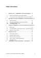
Table of Contents 1. Getting to know 1.1 What is LONWORKS® Communication Module ? ................... 1-1 1.2 The construction of the LONWORKS® Communication Module1-2 2. Mounting and wiring the LONWORKS® Communication Module…2-1 2.1 General guidelines .................................................................... 2-1 2.2 2.2.1 2.2.2 Wiring the LONWORKS® Communication Module .................. 2-3 Connecting the power supply ...................................................
1. Getting to know LONWORKS® Communication Module 1.1 What is LONWORKS® Communication Module ? The Local Operating Network (LONW ORKS® Communication Module) communications module is an interface for connecting IDEC SmartRelay onto a LON network. The IDEC SmartRelay communications module has been implemented as a Slave module for the IDEC SmartRelay control module. The module supports communication between the IDEC SmartRelay Master and external LON devices via a LON.
1.
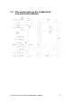
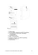
1 6 2 3 4 5 8 7 1. Power supply 2. Bus lock slider, interface to the IDEC SmartRelay 3. The RUN/STOP LED for IDEC SmartRelay communication 4. The SERVICE LED 5. Input - LON connection 6. Expansion interface to the IDEC SmartRelay 7. Mechanical coding - pin 8.
2. Mounting and wiring the LONWORKS® Communication Module 2.1 General guidelines The following guidelines should be observed when mounting wiring your LONW ORKS® Communication Module: - When wiring the LONW ORKS® Communication Module, make certain that you follow all of the applicable and legally binding standards. Observe all of the relevant national and regional regulations when installing and operating the device.
Please notice: - The LONW ORKS® Communication Module must have its own power supply (24 V AC/DC). NOTE This module may only be mounted and wired by qualified personnel, who know and observe the generally applicable guidelines and applicable regulations and standards. Observe the assembly and disassembly instructions in the IDEC SmartRelay manual. WARNING The expansion module may only inserted or removed when the power is off.
2.2 Wiring the LONWORKS® Communication Module To wire the LONW ORKS® Communication Module, use a screwdriver with 3 mm wide blade. - You do not need to use wire end ferrules when clamping the wires. NOTE After the installation, the terminals must be covered. To protect personnel against unintentional contact with the portions of the LONW ORKS® Communication Module that are conducting electricity, the appropriate national and local standards must be observed.
2.2.1 Connecting the power supply The LONW ORKS® Communication Module has been designed to serve as a Slave module for the IDEC SmartRelay controller. It must be connected to a 24 V AC/DC supply voltage. Please observe the relevant instructions that are found in the product information that was included with your equipment as well as the technical data regarding the permissible voltage tolerances, main frequency and current consumption.
2.2.2 Connecting the LON This connection is made using the two screw terminals A-B. You can start the programming by pressing the “Service ¯” button. NOTE Don't apply force when pressing the “Service ¯” button. When contact has been made, the LED will light up in orange.
3. Putting the LONWORKS® Communication Module into operation A LONMARK certified application was loaded into the LON module at the factory. 3.1 Step-by-step 1. Interrupt the voltage to the IDEC SmartRelay. (The IDEC SmartRelay and its modules do not have power switches.) 2. Mount the LONW ORKS® Communication Module 3. Connect the power supply to the LONW ORKS® Communication Module. 4. Connect the LON bus lines to the LONW ORKS® Communication Module. 5.
3.2 The LONWORKS® Communication Module operational status The LONW ORKS® Communication Module is a IDEC SmartRelay expansion module. This module has two LED displays: “RUN/STOP” LED Communication with the IDEC SmartRelay “SERVICE” LED Service LED Green (RUN) The LONW ORKS® Communication Module is communicating with the device on the left.
3.3 Behavior in case of a fault IDEC SmartRelay - Power failure If the power to the IDEC SmartRelay fails or the communications with the IDEC SmartRelay Master or the communications partner to the left is interrupted, the outputs will be set to 0. The “RUN/STOP” LED will light in RED after one second. IDEC SmartRelay - Power returns The IDEC SmartRelay will startup and the LONW ORKS® Communication Module will send the parameterized status.
4. Supported functions The LONW ORKS® Communication Module handles the communications between: - The IDEC SmartRelay and LON - Supports virtual inputs and outputs for the communication via the LON. 4.1 Virtual inputs / outputs The standard LONW ORKS® Communication Module application fills the complete IDEC SmartRelay process image. A1 A2 I1 I2 I3 I4 I5 I6 I7 I8 FL1B-H12RCE Q1 Q2 Q3 FL1B-CL1C12 I1 I2 I3 I4 I5 I6 I7 I8 FL1B-H12RCE Q1 Q2 Q3 A3 ... A8 I9 ... I24 Q5 ...
FL1B-M08B2R2 FL1B-CL1C12 I1 I2 I3 I4 I5 I6 I7 I8 1 I9 Q9 I1 Q16 2 I9I10I11I12 & 3 Q1 I14 Q6 Q1 I13 Q2 Q3 Q4 Q5 Q6 Q7 Q8 I13 ... I24 LON Q9 ... Q16 1. To map the IDEC SmartRelay inputs (I1 to I8/I12) as outputs on the BUS, these must be joined with free virtual BUS outputs (Q5/Q9 to Q12) in the IDEC SmartRelay application. 2. Operations (basic functions BF / special functions SF) useable within the IDEC SmartRelay application (feedback value). 3.
4.2 Available network variables The LONW ORKS® Communication Module’s standard LON application contains the network variables described below.
Assignment of the SNVT to the inputs and outputs Digital outputs SNVT SNVT_switch SNVT_occupancy SNVT_tod_event Digital inputs SNVT_switch SNVT_occupancy Analog inputs SNVT_temp_p SNVT_lux SNVT_switch SNVT_lev_percent Name nvoSwitchDO051 nvoSwitchDO061 nvoSwitchDO071 nvoSwitchDO081 nvoSwitchDO091 nvoSwitchDO101 nvoSwitchDO111 nvoSwitchDO121 nvoOccDO131 nvoOccDO141 nvoTodDO151 nvoTodDO161 nviSwitchDI091 nviSwitchDI101 nviSwitchDI111 nviSwitchDI121 nviSwitchDI131 nviSwitchDI141 nviSwitchDI151 nviSwitch
4.3 LON configuration parameters All of the digital outputs are configured with a “Send Heartbeat”. The LON application is configured using the Config Network Variables. The following SCPT are available.
4.4 Inputs / Outputs – special considerations Allocating the IDEC SmartRelay inputs/outputs All of the inputs/outputs, which are physically allocated on the IDEC SmartRelay or an expansion module, are not available for allocation as virtual inputs/outputs. Only the outputs on additional I/O modules can be issued in parallel to the LON.
5. LONWORKS® Communication Module - Specifications Electrical Data Supply voltage Permissible range Current consumption Data transmission rate - LON Physical Construction Dimensions (W x H x D) Weight Mounting options Connections IDEC SmartRelay connection LON connection (TP/FT-10) Max. torque Power supply Max. torque Standard bus lines to use Environmental Conditions Permissible operating temperature Storage and transport temperatures Humidity 24 V AC -15% +10% max.
Safety Protection standard Radio interference suppression Certification Overvoltage protection Fuse Order Data IDEC SmartRelay Expansion Module LONW ORKS® Communication Module IP 20 EN 55011 (Limit Value Class B) CE UL 508 VDE 0631 IEC 61131-2 80 mA slow action fuse FL1B-CL1C12 LONW ORKS® Communication Module User’s Manual 5-2
6. Index Mechanical coding - pin ...... 1-3 Power supply ....................... 1-3 RUN/STOP LED.................. 1-3 Service button...................... 1-3 SERVICE LED .................... 1-3 slider .................................... 1-3 SNVT_lev_percent........ 4-3, 4-4 SNVT_lux .............................4-3 SNVT_obj_request ...............4-3 SNVT_obj_status .................4-3 SNVT_occupancy ..........4-3, 4-4 SNVT_switch ................4-3, 4-4 SNVT_temp_p ...............