Smart Vision Sensor INSTRUCTION MANUAL www.vision-sensors-illuminators.
DATASENSOR S.p.A. Via Lavino 265 40050 Monte S. Pietro - Bologna - Italy Tel: +39 051 6765611 Fax: +39 051 6759324 http://www.datasensor.com E-mail: info@datasensor.com DATASENSOR S.p.A. reserves the right to make changes or improvements to products at any time without prior notice. 826003840 Rev.
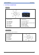
Instruction Manual SVS1 Series INDEX 1. GENERAL INFORMATION ...................................................................................................................1 1.1. Conventions used in the manual .................................................................................................1 1.2. General description......................................................................................................................1 1.3. Available models................................
Instruction Manual SVS1 Series 14. TUTORIAL ...........................................................................................................................................71 14.1. Digital image.........................................................................................................................71 14.2. Machine vision......................................................................................................................72 14.3. General comments on lighting .....
Instruction Manual SVS1 Series 1. GENERAL INFORMATION 1.1. Conventions used in the manual This manual has been developed to provide clear and precise instructions on how to use the SVS1 system. For more detailed information on the algorithms and techniques referenced in the manual, please find ) present throughout the text which refer to Chap.14 - TUTORIAL. symbols such as ( Boxed text provides definitions to ensure better understanding of the specific topic. Examples are printed in italics.
Instruction Manual SVS1 Series 2.
Instruction Manual SVS1 Series 3.
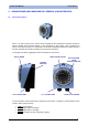
Instruction Manual SVS1 Series 4. VISION SENSOR AND CONFIGURATOR: GENERAL CHARACTERISTICS 4.1. SVS1 Vision Sensor SVS1 is an ultra compact vision sensor which integrates all the photoelectric elements required to perform reliable control activities based on the comparison of two images. Once configured, the sensor can therefore function in a "stand-alone" mode and automatically acquires an image, controls it and then activates the outputs according to the result of the inspection.
Instruction Manual SVS1 Series The Teach button functions will be explained in more detail successively (Chapter 8). TEACH-IN BUTTON 1 4.2. 2 3 4 Installing the sensor The correct position of the vision sensor is essential in order to function properly. There are various aspects to be considered during installation, which have to be evaluated. The following chart summarises the main aspects to consider regarding positioning.
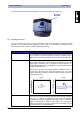
Instruction Manual SVS1 Series Angles In order to avoid reflections on the target object, it is recommended, where possible, to angle the sensor by a few degrees compared to the vertical axis of the target object. Fixing the sensor The SVS1 must be fixed firmly to a stable support, which is not subject to vibrations and protected from contact with any liquids. The catalogue stocks a range of brackets which are specifically designed to support the sensor.
Instruction Manual 4.3. SVS1 Series VSC Configurator The VSC configurator allows the installer to quickly and easily adjust the sensor settings. Once the SVS1 has been connected, the installer can instantly access all the sensor functions, from the creation of a new inspection, to modification of parameters, from the viewing of the results and statistics to the management of digital outputs.
Instruction Manual 4.4. SVS1 Series Installing the configurator There is a slot on the back of the VSC configurator which allows the user to connect the device to a DIN Rail. During installation it is therefore sufficient to wedge the configurator on the rail and block it in place using the two white locking clips. Locking clips Slot for the DIN Rail DIN Rail It is also possible to install the VSC configuratore on a panel. All the accessories for this kind of installation are included in the package.
Instruction Manual SVS1 Series First, place the rubber seal around the body of the configurator paying attention to the shape of it. Rubber seal Then fix the configurator to the panel by using the two locking screws and the rubber caps.
Instruction Manual 4.5. SVS1 Series Hardware connections Connect the power and I/O cable (CS-A1-06-B-xx) inserting it into the connector identified by the (PWR-I/O) icon. PWR-I/O Connect SVS1 to the VSC using the relative connection cable (SVS-CV-VSC-xx). TO VSC Warning • Insert the cable into the correct connector following the key indications inside the body.
Instruction Manual 4.6. Safety recommendations • • • • • • • • • • 11 SVS1 Series Read the instruction manual carefully before installing the sensor and configurator. Make sure that the product is suitable for the system that you intend to set up. Connect the cables to the devices with the poles in the right direction. Power up the devices following the instructions contained in the Manual. Protect all devices against dust, dirt and humidity.
Instruction Manual SVS1 Series 5. INSPECTION CONFIGURATION USING VSC 5.1. Introduction The configuration of the SVS1 vision sensor can only be performed using the VSC unit. This chapter provides the basic procedures to follow in order to programme the sensor settings correctly. Chapters 6 and 7 provide further details on the various configuration options and a more complete panorama on the SVS1 functions.
Instruction Manual 5.3. SVS1 Series General considerations A correct configuration based on the acquisition of a good-quality reference image is necessary to ensure accurate inspection. The term inspection means the set of operations the sensor performs to check the features of an object for compliance with certain specifications. Each individual object is compared to the reference image to determine whether it meets the specified requirements.
Instruction Manual SVS1 Series NOTE: if no inspection is saved on the SVS1 sensor (for instance, the first time it is switched on) the system will display the "Vision Tool" menu from where the user can select the control to be used. For symbol on Page 14. The camera further details, please refer to the paragraph marked with the settings explained in this section can be performed at any moment in time. To configure the inspection option it is necessary to start from Setup Mode.
Instruction Manual Parameter Internal illuminator External illuminator Exposure time Gain Negative SVS1 Series Description Select or deselect the option to enable/disable the illuminator fitted on the sensor. Select or deselect the option to enable/disable the strobe signal that the sensor can use to pilot the external illuminator. The exposure time identifies the period that the lens remains open and allows light to reach the CMOS mounted on the sensor.
Instruction Manual SVS1 Series If you wish to exit the control panel without saving the modifications, simply press the ESC button. The configurator will display a pop-up message asking the user if he wishes to save the settings. Select NO using the ARROWS and press SET to exit without saving. Once you have completed the camera settings, you can select the inspection tool. To select this option, use the ARROWS on the VISION TOOL icon and press the SET button.
Instruction Manual SVS1 Series Width Control of the size of details Edge Counting Counting of details along an edge Once the inspection tool has been selected, it is necessary to position and size the regions of interest (ROI) to be monitored. The meaning of the ROI varies according to the control tool selected. The chart below provides a rough indication on the meanings. Please refer to Chapter 7 for further details.
Instruction Manual SVS1 Series If you wish to modify the ROI size, select the Resize ROI from the Setup menu (using the SET button again). It is now possible to increase or decrease the ROI size using the ARROW buttons. The size (expressed in pixels) of the current ROI are displayed at the bottom of the screen. Once you have achieved the desired size, press the TEACH button to save the settings and return to the Setup menu.
Instruction Manual 5.5. SVS1 Series Step 2 - Configuration of the selected inspection tool In step 2 of the configuration process you will define the settings which will regulate the inspection tool selected in step 1. The configurator display is basically organised as seen in step 1. The settings that the user can modify are displayed on the right, whilst the rest of the screen displays the image acquired by the sensor.
Instruction Manual 5.6. SVS1 Series Step 3 - Inspection tool function check In Monitor Mode, it is possible to check that the inspection tool settings entered during the configuration step function correctly. The user can choose from five different monitoring modes. The chart below provides a description of the main features of the five available modes with instructions on how to enable viewing.
Instruction Manual SVS1 Series • Failure (%) % of failed inspections of the total number executed It is now possible to modify the view scale for the graph below using the RIGHT/LEFT ARROW buttons. In particular: The graph is compressed along the xaxis using a factor of 10. The graph is compressed along the xaxis using a factor of 100. Press SET to exit the statistics mode.
Instruction Manual SVS1 Series NOTE: in Monitor Mode it is possible, as already mentioned, to check that the inspection settings function properly. It is however important to highlight that the inspection displayed on the VSC does not correspond to that saved on the sensor until the user saves it in one of the memory slots on the sensor.
Instruction Manual SVS1 Series The standard save procedure is described in detail in paragraphs 5.7 and 6.3. It is also possible to perform a quick save of the settings as follows. Press the TEACH button when in Monitor mode. A window will appear with a summary of the modifications made to the current inspection and the memory slot currently enabled. To save the setting, simply press the TEACH button again. Press ESC if you wish to return to Monitor mode. 5.7.
Instruction Manual SVS1 Series As seen in the image below, it is possible to assign a different behaviour to each output. Option Part pass Part fail Busy-Ready Error Toggle Disable Behaviour The output is enabled when the inspection gives a positive result. If a failure occurs it remains low. The output is enabled if a failure occurs. If the inspection gives a positive result, it remains disabled. The output takes on value 1 (Busy) for the entire time the sensor takes to acquire and process the image.
Instruction Manual SVS1 Series Two other parameters which can be configured can be seen at the bottom of the screen. • • Duration this indicates the length of time (in ms) the output must maintain the last acquired value; this is mainly used for Part Present, Part Pass and Part Fail modes. Delay indicates after how long the output shall display the last acquired result.
Instruction Manual SVS1 Series On completing these configuration procedures, the user can: • • disconnect the VSC and use the sensor in stand-alone mode use the VSC to view the results of the inspection.
Instruction Manual 6. SVS1 Series VSC CONFIGURATOR: ADVANCED FUNCTIONS The previous chapter described the procedure used to create a new inspection for SVS1. Besides the functions illustrated above, there are other user settings on the VSC configurator which can be reached from the System menu. These functions are listed and individually described below. 6.1. Output From the Output Settings menu it is possible to configure the 3 digital outputs on the sensor.
Instruction Manual SVS1 Series By default the three outputs have the following settings: • • • OUTPUT 1: Part pass OUTPUT 2: Part fail OUTPUT 3: Busy-Ready To modify the behaviour of the outputs, move the cursor with the ARROWS then use SET to select the desired option. Each output can also function in negative logic. On enabling this option, the output will behave in the opposite manner compared to standard mode: that is it will take value 1 instead of 0 and vice-versa.
Instruction Manual 6.2. SVS1 Series Trigger Mode The term trigger means a signal generated by an event that provokes another event. In our instance, the trigger is a signal generated by a device that triggers image acquisition. When the sensor is used to inspect moving objects, it is important to ensure that the object is inside the detection area at the precise instant the image is captured for processing.
Instruction Manual SVS1 Series Trigger hardware The image acquisition signal is sent by an external device (e.g. a photocell), the signal naturally has a rising and falling edge. Photocell TRIGGER Image acquisition Control Measurement OK / FAIL INSPECTION If the "Rising Edge" is selected, the image acquisition signal follows the rising edge of the external device. If the "Falling Edge" is selected, the image acquisition signal follows the falling edge of the external device.
Instruction Manual SVS1 Series It is also possible to set a delayed image acquisition compared to the trigger signal received for both hardware triggers. To set the delay value, simply use the slider found at the bottom of the screen using the RIGHT/LEFT ARROW buttons. Example: The image acquisition is delayed by 150 ms compared to the rising edge of the trigger signal. 6.3. Bankset The term bankset identifies the control panel used to manage the databank areas available on the sensor.
Instruction Manual SVS1 Series To select the memory bank you wish to use, move the cursor using the ARROW buttons and press the SET button to confirm. When you are on the selected memory bank, you can perform three different operations which can be recalled using the icons at the bottom of the screen: • Load: This loads the inspection memorised on the selected bank. Press the SET button to load the selected inspection onto the device.
Instruction Manual • SVS1 Series Clear: This deletes the inspection memorised on the selected bank. Once the SET button has been pressed, the device requests delete confirmation. The user can select the option using the ARROW buttons and then press SET to confirm. It is possible to exit the bankset at any time by pressing the ESC button. 6.4. Fail Inspector The fail inspector is a tool which permits the user to recall the images of the last inspection failures.
Instruction Manual Label Tool ROI X Co-ord. ROI Y Co-ord.
Instruction Manual 6.6. SVS1 Series Menu mode It is possible to select which interface to use during configuration of the inspection tool. The user can choose from two different options: Standard Only the main configuration settings can be accessed Expert All the settings can be selected and modified by the user All the parameters which can be set by the user are listed individually in the next chapter. The settings which can only be accessed in expert mode are marked with the symbol . 6.7.
Instruction Manual SVS1 Series It is now possible to enter a new password consisting in a sequence of four buttons on the keyboard. Once the password has been entered, press SET to confirm. The password status switches from Disabled to Enabled. When the password is enabled, the user can perform either of the following operations: • Modify the password: To modify the current password, select the Modify option and then press SET to confirm.
Instruction Manual SVS1 Series NOTE: when the password is Enabled, everytime the user tries to leave the monitor mode, the device requests to enter the current password. Once entered the password, the user can go to the other configuration panels in which it is possible to change the parameter settings. After 5 minutes without changes, the device goes back to monitor mode and it enables the password again. 6.8. Reset The reset function allows the user to reboot the VSC configurator.
Instruction Manual SVS1 Series 7. CONTROLS 7.1. Remarks These controls play a key role in the inspection process: they are used to perform controls/checks and measurement on acquired images. Entering the controls is an operating step of the inspection.
Instruction Manual 7.2. SVS1 Series Brightness • Description The term brightness means the "brightness" attribute of an image. Once the ROI has been set, the control will calculate the average brightness value of the pixels. • Selection • Positioning Select the control and press SET on the corresponding icon to create the rectangular ROI in the middle of the field range. To modify the position of the ROI, move to the Move ROI icon and then press SET.
Instruction Manual • SVS1 Series Result If the average brightness value inside the ROI is above the set threshold, the result will be positive (green colour indicator and ROI edge) if it is below the threshold, the result will be negative (red colour indicator and ROI edge) • Example We would like to add the "Brightness" test to the current inspection to check for the presence of magnetic strips on badges. Select "Brightness" from the Controls menu and press SET.
Instruction Manual SVS1 Series We can acces the Adjust mode by pressing the STATUS button. Let's increase the acceptance threshold slightly using the ARROW UP button. Now press the STATUS button to enter Monitor Mode and check that the tool functions properly. As the result is satisfying, press STATUS again and move on to defining the behaviour of the outputs. Let's associate output 1 to the Part Pass behaviour and output 2 to the Toggle behaviour (leaving output 3 disabled).
Instruction Manual 7.3. SVS1 Series Contrast • Description The term contrast indicates the ratio between the brightness of the lightest pixel and that of the darkest pixel in an image. Images with excessively high contrast tend to have only black and white areas, whilst images with low contrast tend to look grey. • Selection • Positioning Select the control and press SET on the corresponding icon to create the rectangular ROI in the middle of the field range.
Instruction Manual SVS1 Series To modify the position of the ROI, move to the Move ROI icon and then press SET. It is now possible to move the ROI using the ARROW buttons. Once you have achieved the desired position, press the TEACH button to return to the Setup menu. If you wish to modify the ROI size, select the Resize ROI from the Setup menu (using the SET button again). It is now possible to increase or decrease the ROI size using the ARROW buttons.
Instruction Manual SVS1 Series The image is now acceptable, so we must resize and position the ROI accordingly: follow the instructions provided previously during this procedure. We can access the Adjust mode by pressing the STATUS button. If the control fails even when there is a stamp, increase the control sensitivity a little to raise the contrast between the stamp and the envelope. To do this use the RIGHT ARROW to view the sensitivity setting and then use the ARROW UP button to increase the value.
Instruction Manual SVS1 Series Let's associate output 1 to the Part Pass behaviour, output 2 to the Part Fail behaviour and output 3 Busy/Ready. Press TEACH to save the modifications. Now let's save the bank on the sensor. Enter the Bankset menu and save the inspection in memory bank 1. Press the ESC button to return to Monitor mode.
Instruction Manual 7.4. SVS1 Series Position • Description This control allows you to detect the edge (edge detection inside the relative ROI. ) and the position of the object Based on the first derivative of the pixel brightness variation function, the maximum positive peak is identified if control is targeting a positive edge, or the maximum negative peak is identified when targeting a negative edge.
Instruction Manual • SVS1 Series Parameters: Min Position Expected This allows you to specify the minimum value of the detectable position. Max. Position Expected This allows you to specify the maximum value of the detectable position. • Sensitivity This represents the sensitivity level, that is the level of edge detection precision. Set sensitivity affects processing results; the lower the sensitivity, the greater the accuracy.
Instruction Manual SVS1 Series Now we must perform the ROI positioning and resizing procedures: follow the instructions provided earlier during this procedure. We can access the Adjust mode by pressing the STATUS button. Let's increase the minimum position value slightly using the ARROW UP button. Now press the STATUS button to enter Monitor Mode and check that the tool functions properly. The sensor now behaves as required.
Instruction Manual SVS1 Series Now let's save the bank on the sensor. Enter the Bankset menu and save the inspection in memory bank 1. Press the ESC button to return to Monitor mode. 7.5. Width • Description This control is also termed "gauge" and lets you measure the distance between two points. ) are used to detect the edges of an object, and calculate the The edge detection techniques ( distance between the edges.
Instruction Manual SVS1 Series To modify the position of the ROI, move to the Move ROI icon and then press SET. It is now possible to move the ROI using the ARROW buttons. Once you have achieved the desired position, press the TEACH button to return to the Setup menu. If you wish to modify the ROI size, select the Resize ROI from the Setup menu (using the SET button again). It is now possible to increase or decrease the ROI size using the ARROW buttons.
Instruction Manual • SVS1 Series Result If the calculated width value is between the minimum and maximum values set by the user, the control gives a positive result. If no edges are found, or their reciprocal distances are not within the two defined limits, the result will be negative. • Example Let's add a "width" control to the current inspection tool, so we can check that a box is closed correctly. Let's select "Width" from the Controls menu and then press the SET button.
Instruction Manual SVS1 Series The sensor now behaves as required. As the result is satisfying, press STATUS again and move on to defining the behaviour of the outputs. Let's associate output 1 to the Part Pass behaviour and output 2 to the Busy/Ready behaviour. Press TEACH to save the modifications. Now let's save the bank on the sensor. Enter the Bankset menu and save the inspection in memory bank 1. Press the ESC button to return to Monitor mode.
Instruction Manual 7.6. SVS1 Series Edge count • Description ) that are within a specific ROI. This control allows you to detect all the edges (edge detection Based on the first derivative of the pixel brightness variation function, the maximum positive peak is identified if control is targeting a positive edge, or the maximum negative peak is identified when targeting a negative edge.
Instruction Manual • SVS1 Series Parameters: Min edges Expected This allows you to specify the minimum number of detectable edges. Max. edges Expected This allows you to specify the maximum number of detectable edges. • Sensitivity This represents the sensitivity level, that is the level of edge detection precision. Set sensitivity affects processing results; the lower the sensitivity, the greater the accuracy, hence, the more edges will be found.
Instruction Manual SVS1 Series The ROI now has to be suitably resized and positioned: follow the instructions provided earlier during this procedure. We access the Adjust mode by pressing the STATUS button. Let's increase the minimum edge limit value to 3 using the ARROW UP button. Use the RIGHT ARROW button to set the type of variation to be detected. Use the ARROW UP button to see the Black to White value. Now press the STATUS button to enter Monitor Mode and check that the tool functions properly.
Instruction Manual SVS1 Series Let's associate output 1 to the Part Pass behaviour and output 2 to the Part Fail behaviour. Press TEACH to save the modifications. Now let's save the bank on the sensor. Enter the Bankset menu and save the inspection in memory bank 1. Press the ESC button to return to Monitor mode. 7.7. Pattern Match • Description The term pattern match signifies a process that searches for a pattern similar to the master image inside the target image using its brightness matrix.
Instruction Manual • Selection • Positioning SVS1 Series The positioning and resizing of the ROI for the Pattern Match control is different compared to what we have seen for the other inspection tools. During the setup phase, it is in fact necessary to define the pattern to be searched inside the image and also the section of the area which has to be searched.
Instruction Manual • SVS1 Series Parameters Expected Threshold used to assess the result. This indicates to what extent the detected area in the ROI must match the sample image in order to be considered as valid (100% perfect match, 0% ... ). • Sensitivity This identifies the accuracy with which the pattern is searched inside the acquired image. The higher the desired quality, the more time is required to complete the processing.
Instruction Manual SVS1 Series We now go to Adjust mode by pressing the STATUS button. Let's increase the expected value slightly using the ARROW UP button as we want exact replicas of the original logo. Now press the STATUS button to enter Monitor Mode and check that the tool functions properly. The sensor now behaves correctly. As the result is satisfying, press STATUS again and move on to defining the behaviour of the outputs.
Instruction Manual SVS1 Series Press the ESC button to return to Monitor mode. 7.8. OCV • Description The OCV (Optical Character Verification) operator is able to check whether the text contained in an image is identical to that in the reference image. This control is not able to interpret the text it reads or send it to output. It simply checks that the detected string is identical to the reference sample.
Instruction Manual SVS1 Series To modify the position of the ROI, move to the Move ROI icon and then press SET. It is now possible to move the ROI using the ARROW buttons. Once you have achieved the desired position, press the TEACH button to return to the Setup menu. If you wish to modify the ROI size, select the Resize ROI from the Setup menu (using the SET button again). It is now possible to increase or decrease the ROI size using the ARROW buttons.
Instruction Manual • SVS1 Series Example Let's add an "OCV" control to the current inspection tool, so we can check that a web address is printed correctly on boxes. Let's select "OCV" from the Controls menu and then press the SET button. A rectangular default ROI will appear in the centre of the image. The ROI must be resized and positioned as required: follow the instructions provided earlier during this procedure. We can access the Adjust mode by pressing the STATUS button.
Instruction Manual SVS1 Series The sensor now behaves correctly. As the result is satisfying, press STATUS again and move on to defining the behaviour of the outputs. Let's associate output 1 to the Part Pass behaviour and output 2 to the Part Fail behaviour. Press TEACH to save the modifications. Now let's save the bank on the sensor. Enter the Bankset menu and save the inspection in memory bank 1. Press the ESC button to return to Monitor mode.
Instruction Manual SVS1 Series 8. TEACH BUTTON The Teach button located on the upper part of the sensor allows you to reboot the device in Recovery mode. This function is needed to update the firmware of the sensor. To enable the recovery procedure, boot the device whilst holding the TEACH button down until the output LEDs (the two central ones) start to flash; this means the sensor is loading its recovery software.
Instruction Manual SVS1 Series 9. SELECTING AN INSPECTION USING THE DIGITAL INPUTS By using a special protocol it is possible to use the digital inputs to select the inspection to be performed on the SVS. The protocol comprises a prologue followed by an epilogue. The prologue consists in 3 impulses with a minimum duration of 10 msec and a 50% duty cycle.
Instruction Manual SVS1 Series 10. CHECKS AND PERIODIC MAINTENANCE Correct maintenance consists in the removal of dust or foreign objects from the sensor. Remove any dust build-up from sensor body using a soft cloth; if needed, dampen cloth slightly with a mild detergent solution. To clean off dust and fingerprints from the lenses, use an anti-static compressed air can. Use a cloth and a specific lens detergent to remove any residue.
Instruction Manual SVS1 Series 11.
Instruction Manual SVS1 Series 12.
Instruction Manual SVS1 Series 13.
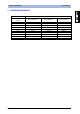
Instruction Manual SVS1 Series MODEL DESCRIPTION ORDER No.
Instruction Manual SVS1 Series 14. TUTORIAL 14.1. Digital image Digitisation allows real images acquired by a camera to be treated using a processor. This is done in two steps: • sampling: image is divided into a dot matrix. Dots are termed picture elements (or more commonly pixels); • quantisation: each pixel is associated to a numeric value. Such information may signify point brightness for grey scale images (0 = black, 255 = white), or three values (Red-Blue-Green, RGB coding) for colour images.
Instruction Manual SVS1 Series Machine vision 14.2. This is a specific branch of Computer Vision (or "artificial vision"). Computer vision is a generic concept which applies to all processes aimed at extracting information from images. On the other hand, machine vision has a specific purpose, i.e. control the operation of equipment and machinery in industrial applications (such as manufacturing lines or good handling applications).
Instruction Manual 14.4. SVS1 Series Lighting options Ring light This technique is suitable for a broad range of applications. The illuminator is mounted directly on the sensor and can illuminate any object placed in front of it. It provides diffused illumination over a small area. o o Advantages: It provides correct levels of illumination even for small sized objects. Reduces shadows caused by object projections.
Instruction Manual Binarization This is a process that converts any given image to a two-level image (in our instance, black and white). Conversion is based on a threshold that classifies the individual pixels as "level 255" (or "white") or "level 0" (or "black") depending on whether they are above or below set threshold. Let us consider a shot of a dark object on a bright background.
Instruction Manual 14.6. SVS1 Series Edge / Edge Detection The term "edge" signifies the contour of the object shown in an image. From an operational viewpoint, what happens is that the system detects the difference in the brightness of adjacent pixels compared to a certain threshold value.
Instruction Manual 14.7. SVS1 Series Inspection times Total inspection duration depends on three factors: ) • Exposure time ( • Acquisition time • Processing time Exposure time: time period during which the acquisition device is exposed to light. The longer the exposure time, the greater the quantity of light entering the device.
Instruction Manual 14.9. SVS1 Series Exposure Exposure time determines how long the image acquisition device must remain exposed to light. Image quality depends on this parameter, that is determined based on: • Lens aperture; • Exposure. The term Lens aperture denotes the ratio of lens length to lens width. A longer lens (where light travels a longer distance) will have a higher ratio and will provide less strength. Conversely, a shorter lens features a lower ratio (fast lens).
Instruction Manual SVS1 Series 15. GLOSSARY • Algorithm: a combination of instructions that lead to the solution of a problem through a series of steps; • Area of inspection: this corresponds to the area of interest acquired by the sensor, or part of the same, which is then processed; • CMOS: device that acquires the images.