
Datasheet


Precautions & Instructions
Operating Instructions
Safety Precautions
Turn off the power to CW series switches before installation, removal,
wiring and maintenance. Failure to turn power off may cause electrical
shocks or fire hazard.
When wiring, use wires of a proper size to meet the voltage and current
requirements. Tighten the M3.5 terminal screws to a tightening torque of
1.0 to 1.3 N·m. Failure to tighten the terminal screws may cause over-
heating and fire.
Notes for Operation
When using the CW series switches in a
safety-related circuit of a control system,
observe safety rules and regulations of
each country concerning particular applica-
tions of the actual machines and facilities.
Perform risk assessment before operation
to ensure safety.
Operating Conditions
In corrosive gas or high-temperature, high-
humidity environments, contact failure due to
corrosion or color change or breakage of the
housing may occur.
Main parts of the CW series switches are
made of plastic. Do not scratch the surface
with a sharp object or apply excessive electric
shock or load, otherwise the switches may be
damaged. In particular, keep the button, lens
and bezel from such damage, otherwise ap-
pearance and function may be impaired.
Do not apply detergents, cutting oils, or
chemicals which may impair the function and
appearance of the CW series switches.
Panel Mounting
First remove the contact block and then the
locking ring from the operator. Insert the
operator into the panel cut-out from the front,
tighten the locking ring from the back, then
install the contact block to the operator.
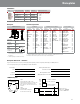
Mounting Hole
1. Mounting hole dimensions are in compli-
ance with IEC60947-5-1.
2. If the anti-rotation projection is removed
from the bezel, CW series switches can be
mounted in ø22.3mm mounting holes. To
remove the anti-rotation projection, remove
the gasket and use cutting pliers to break
the projection.
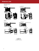
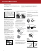
Illuminated Pushbuttons and Pilot Lights
Removing the Lens
To remove the lens from an illuminated pushbutton
or pilot light, insert a flat screwdriver under the
flange of the lens at 90° from the TOP marking and
twist the screwdriver.
Do not insert the screwdriver too far and do not ap-
ply excessive force to the lens, otherwise the bezel
surface may be damaged.
Screwdriver Insertion Direction
TOP Marking
TOP Marking
Screwdriver Insertion Angle
Approx. 30°
Panel Surface
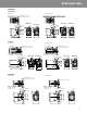
Installing the Lens
Turn the groove in the lens to the TOP marking on
the operator housing. With the groove aligned with
the ridge, press the lens in.
TOP Marking
Groove in the Lens
Ridge
Marking
Marking film can be applied for inscriptions or
identification.
Applicable Marking Film Size
Illuminated Pushbutton (Round Flush)
Pilot Light (Round Flush, Round Extended)
Illuminated Pushbutton
(Round Extended)
ø15.
9
13.8
12.6
ø15.
9
Thickness: 0.2 mm maximum
Film material: Polyester (recommended)
Note: Film is not supplied and must be provided by the user.
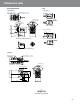
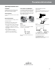
Removing and Installing the Contact Unit
1. To remove the contact block from the opera-
tor, push the yellow locking lever and turn it
to the left.
Locking Lever
2. To install, align the TOP marking on the
operator with the TOP marking on the
contact block mounting adaptor, and turn
the locking lever to the right.
Installation in Panel Cut-out
Remove the locking ring from the operator.
With the anti-rotation projection on the opera-
tor aligned with the recess in the mounting
hole, insert the operator into the mounting
hole. Tighten the locking ring from the rear of
the panel.
Note for Panel Mounting
When installing the operator in a panel cut-
out, use the optional locking ring wrench
(MW9Z-T1) to tighten the locking ring to a
recommended tightening torque of 1.2 N·m. Do
not use pliers and do not tighten excessively,
otherwise the operator may be damaged.
TOP marking on selector and key
selector switches
Locking Ring
Panel
TOP marking on illuminated
pushbuttons, pushbuttons
and pilot lights
Anti-rotation projection
Recess in mounting hole
22