
Datasheet
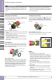
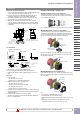
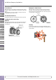
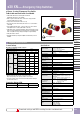

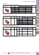
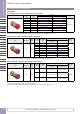
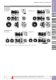
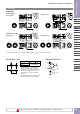
Table Of Contents

Download catalogs and CAD from http://asia.idec.com/downloads
D-044
APEM
Switches &
Pilot Lights
Control Boxes
Emergency
Stop Switches
Enabling
Switches
Safety Products
Explosion Proof
Terminal Blocks
Relays & Sockets
Circuit
Protectors
Power Supplies
LED Illumination
Controllers
Operator
Interfaces
Sensors
AUTO-ID
Emergency Stop Switches
X6
XA
XW
XN
SEMI
ø30 XN Series Emergency Stop Switches
Dimensions
61.4
59.9
20.1 18.5
37
43
ø44
33.0
+0.5
0
4.8
+0.2
0
R0.8 max.
ø30.5
+0.5
0
Panel Cut-out
Rubber Gasket
Locking Ring
M3 Terminal Screws
IP20 Cover
XW9Z-VL2MF
Panel Thickness 1 to 6
(*1)
37
Panel Thickness 1 to 6
IP20 Cover
XW9Z-VL2MF
ø44
33.0
+0.5
0
4.8
+0.2
0
R0.8 max.
ø30.5
+0.5
0
Panel Cut-out
61.4
59.9
20.1 18.5
43
Rubber Gasket
Locking Ring
M3 Terminal Screws
Push-ONIlluminated
(*1)
61.4
59.9
20.1 18.5
43
37
ø44
33.0
+0.5
0
4.8
+0.2
0
R0.8 max.
ø30.5
+0.5
0
Panel Cut-out
Panel Thickness 1 to 6
Terminal Cover
XW9Z-VL2M
Rubber Gasket
Locking Ring
M3 Terminal Screws
Push-ONIlluminated
(*1)
61.4
20.1 18.5
43
ø44
33.0
+0.5
0
4.8
+0.2
0
R0.8 max
.
ø30.5
+0.5
0
Panel Cut-out
Rubber Gasket
Locking Ring
M3 Terminal Screws
Panel Thickness 1 to 6
Terminal Cover
XW9Z-VL2M
(*1)
Padlockable
Non-Illuminated
IP20 Fingersafe
w/Terminal Cover
Illuminated/Push-ON
IP20 Fingersafe w/Terminal Cover
*1) Make sure that the panel cut-out is as shown in the drawing as the operator has a projection for anti-rotation.
ø30.5
+0.5
0
X
Y
X1
X2
R
LED
LED chip
Protection Diode
Resistor
X Y
Plastic Bezel
70 mm minimum
Flush Bezel
•The values shown above are the minimum
dimen sions for mounting with other ø30 mm
pushbuttons. For other control units of different
sizes and styles, determine the values accord-
ing to the dimensions, operation, and wiring
convenience.
•For padlockable, determine the values accord ing
to the size and number of padlocks and hasp.
Mounting Hole Layout LED Unit Internal Circuit
Download catalogs and CAD from http://eu.idec.com/downloads