
Datasheet
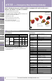
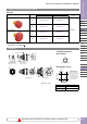
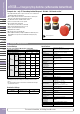
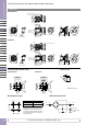
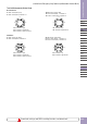
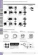
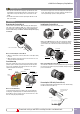
Table Of Contents

Terminal Arrangement (Bottom View)
12
12
TOP
21
21
Left Right
TOP
21
21
12
34
Left Right
12
12
TOP
21
21
Left Right
TOP
21
21
12
34
Left Right
WithNOmonitorcontacts(blue)
NCmaincontacts(black): Terminals1-2
NOmonitorcontacts(blue): Terminals3-4
NCmaincontacts(black)only
NCmaincontacts(black):Terminals1-2
1NC:Terminalsonright
2NC:Terminalsonrightandleft
3NC:Terminalsonright,left,andtop
1NC:Terminalsontop
2NC:Terminalsonrightandleft
Non-illuminated
Illuminated
Left Right
TOP
21
21
12
12
X1 X2
TOP
Left Right
21
21
12
34
X1 X2
LED
LED
Left
Right
TOP
21
21
12
12
X1 X2
TOP
Left Right
21
21
12
34
X1 X2
LED
LED
WithNOmonitorcontacts(blue)
NCmaincontacts(black): Terminals1-2
NOmonitorcontacts(blue):Terminals3-4
NCmaincontactsonly(black)
NCmaincontacts(black):Terminals1-2
1NC:Terminalsonright
2NC:Terminalsonrightandleft
3NC:Terminalsonright,left,andtop
1NC:Terminalsontop
2NC:Terminalsonrightandleft
Download catalogs and CAD from http://asia.idec.com/downloads
D-020
APEM
Switches&
PilotLights
ControlBoxes
Emergency
StopSwitches
Enabling
Switches
SafetyProducts
ExplosionProof
TerminalBlocks
Relays&Sockets
Circuit
Protectors
PowerSupplies
LEDIllumination
Controllers
Operator
Interfaces
Sensors
AUTO-ID
Emergency Stop Switches
X6
XA
XW
XN
SEMI
ø16 XA Series Emergency Stop Switches (w/Removable Contact Block)
Download catalogs and CAD from http://eu.idec.com/downloads