
Installation Guide

iDEAL Paint Spray Booth (PSB-AFCF23ASY)
25
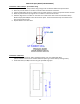
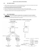
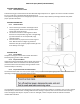
4.16 LIMIT SWITCH WIRING
1. Obtain line power from proper terminal in remote Control Panel and wire it to the first Limit Switch (Local Codes
may require Limit Switches to be wired using rigid sealed off conduit).
2. Run line power from the first Switch to the second Switch.
3. Continue wiring all Switches in this manner to be in series.
4. Return the last line wire to the remote Control Panel and connect it to the proper terminal.
5. Controller in remote Control panel will now control the Air Solenoid in Spray mode and Heat system in Bake
mode (manual override must be reset if tripped) when door(s) are open.
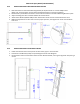
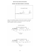
4.17 AIR SOLENOID WIRING
(Example only - Consult wiring diagrams supplied with your equipment for proper installation)
1. Obtain power and common from proper terminals in remote Control Panel and wire them to the Air Solenoid.
2. Air solenoid is now controlled by Control Panel in spray mode.
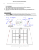
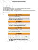
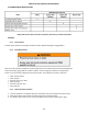
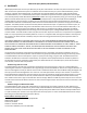
CONTROL PANEL WIRING DIAGRAM – 208-240VAC, 60HZ, 3 PHASE