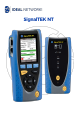
SignalTEK NT
COPYRIGHT NOTICE The information contained in this document is the property of IDEAL INDUSTRIES Ltd. and is supplied without liability for errors and omissions. No part of this document may be reproduced or used except as authorized by contract or other written permission from IDEAL INDUSTRIES Ltd. The copyright and all restrictions on reproduction and use apply to all media in which this information may be placed. IDEAL INDUSTRIES Ltd.
CONTENTS Introduction .......................................................................................................................................................................4 Care of your SignalTEK NT ......................................................................................................................................... 5 Final Disposal ............................................................................................................................................
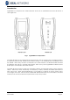
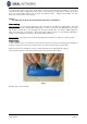
Introduction SignalTEK NT comprises two hand-held units and a set of standard accessories all held in a semi-rigid case. Fig 1 SignalTEK NT components The Near-End unit is the terminal from where all tests are run and stored. The Remote Unit is a loopback terminal that enables performance testing. The Near-End Unit and Remote Unit are paired.
Care of your SignalTEK NT Although light and portable, the SignalTEK NT units are robust and have been designed to operate in a protected outdoor working environment. To ensure reliable operation: Avoid very high or low temperatures - SignalTEK NT is designed to operate between 0°C and +40°C, although you should only charge the batteries between +10°C and +30°C. You can store the unit safely between -20°C and +70°C.
Power SignalTEK NT can be powered from: A rechargeable power module, Directly from power connected to the DC inlet built in to the power module. Power Module Management The power module must be fully charged before you use it for the first time A fully charged power module will support up to five hours of heavy, continuous use. For maximum life of the power module it is recommended to discharge it fully and then recharge it fully at least once a month. The power module is not user-serviceable.
To switch OFF either unit, press and hold the Power button for approximately 1/2 second, a shutdown message is displayed on the screen. The currently stored setup is saved. If the unit does not switch OFF within five seconds, see Master Reset. Always switch OFF the unit before removing the power module. Caution Do NOT remove the power module when the unit is switched on. Power Saving Near-End Unit. Power saving preferences are selected from SETUP>SYSTEM>PREF.
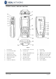
Handset Controls, Indicators and Ports 24 Fig 4 1 RJ 45 port 9 Function keys F1 to F3 17 Link LED 2 RJ 45 activity LED 10 Escape key 18 Status LED 3 RJ 45 link LED 11 Cursor and ENTER keys 19 1000 Mb/s line rate LED 4 Optical port (SFP) 12 ON/OFF button 20 100 Mb/s line rate LED 5 Optical activity LED 13 Power module 21 10 Mb/s line rate LED 6 Optical link LED 14 Charger LED 22 Remote Autotest button 7 USB port 15 DC in connector 23 Power LED 8 LCD color display
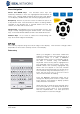
Menu Navigation Cursor and ENTER keys. The arrowed cursor keys are intuitively marked to move the highlighted field between all menu icons, settings fields and drop-down menus that appear on the display. ENTER selects the currently highlighted option. Escape key. Returns to previous screen or hides the options of a drop-down menu. Note that when a value in a settings field is changed, if the Escape key is pressed before the soft key ‘APPLY’, the value will not be stored. Autotest key.
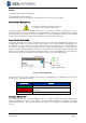
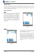
Getting started Press the soft key DETECT (F1) and the Near-End Unit will determine the mode of operation dependent on the services detected. The display will show a home screen with one of four connection symbols. There are two modes of operation, Cable and Ethernet. Cable has one way of connecting, Ethernet has three. Modes of Operation Cable Cable mode is used for Wiremap testing and cable route tracing using the tone generator.
(2) When the Near-End Unit is connected to an active network, using copper or fiber cable, press the soft key DETECT (F1) to display all options available (Fig 9). IP tests can be run. For a full description of these options see – Tests menu description – Ethernet mode, page 25. The detected services are PoE (802.3af/at), ISDN, PBX and Unknown. The connected Port number and LLDP Power are displayed (when available.) The IPv4 and IPv6 addresses assigned to the tester are displayed (when available).
Ports From the home screen press the soft key PORTS (F2), highlight the required port and press ENTER (Fig 11). Tick the check box to always see this screen at startup. Fig 11 Replaceable insert – RJ-45 socket To replace a damaged or worn RJ-45 socket insert proceed as follows: Equipment required: Insert x10. Kit, IDEAL part number 150058 – includes Tool x1 and Replacement 1. Switch the SignalTEK NT off. 2. Remove cables. 3. Carefully push the tool STRAIGHT into the socket.
Setup All user-defined settings and preferences of the SignalTEK NT are set from the SETUP menu. A description of the available settings and preferences is found on pages 14 to 17.
Setup menu descriptions From the home screen, press the soft key SETUP (F3) to display the Setup menu shown in Fig 13. The settings for all tests, functions and preferences can be changed and saved from here. Selecting any of the seven icons will produce the options that follow: Fig 13 Highlight the System icon and press ENTER to access the settings and preferences listed below: Enter your name or your company’s name, address and phone number(s).
Highlight the Tests icon and press ENTER to access the settings and preferences listed below: The two wiretests that follow are available :Set the cable type and color scheme to suit the cable to be tested, crossover allowed y/n, and NVP. NVP is preset at 72% but can be custom set anywhere in the range of 59 to 89% to suit the cable to be tested. Select from three tones. This avoids confusion when a second or third tester is being used on the same installation.
IP Tests continued Set the target URL/Numerical address (select from up to 10 targets stored in the v6 TARGET look up table or edit the currently displayed URL), Count (Number of times to repeat the Ping - 1 to 999999), Pause (Interval between successive Pings - 1 to 5 seconds), Length (Number of bytes in the Ping frame payload - 8 to 1000 bytes).
Enable/disable IPv4 and set IP address as static or dynamic (DHCP) depending on which type your network supports. If Static is selected, enter the numerical address, Netmask, Gateway, DNS1 and DNS2. Enable/disable IPv6 and select address type as Static, Stateless, Stateful (DCHP) depending on which type your network supports. If Static is selected, enter numerical IP address, Prefix (64 or 128), Gateway, DNS1 and DNS2. The factory set MAC address of the tester is displayed.
Tests modes Testing with SignalTEK NT falls into two modes, Cable and Ethernet. Cable mode Cable testing comprises of wiremap tests and a tone generator. When no network or SignalTEK NT Remote Unit is detected, the home screen information bar will read ‘Cable’. When the TESTS icon is selected, the cable tests shown in the menu map at Fig 14 are available.
(3) When a SignalTEK NT Remote Unit is detected through an active network the information bar will read ‘Ethernet’. When the TESTS icon is selected, the Ethernet tests shown at Fig 17 are available. Fig 17 Test menu map – Ethernet testing (3) Tests – run, setup and save To select a test highlight its icon and press Enter. Each test has its own result screen. This is indicated by the test name being shown in the display’s information bar. Press the soft key RUN (F1) to start the test.
Tests menu description – Cable mode When the TESTS icon from the cable mode home screen is selected, Fig 18, the available tests will be displayed, Fig 19. Fig 18 Fig 19 After any one of the three available tests from the menu is selected, the soft keys RUN and SETUP will appear: Wiremap When the soft key RUN (F1) is pressed a wiremap test will be run on the cable currently connected to the tester’s RJ45 port.
Note that for the example of a Wiremap test shown above; if the option ‘XOver Allowed’ had been checked in the Wiremap SETUP options, the results would be displayed as shown in Fig 22 and Fig 23. Fig 23 Fig 22 The wiremap tests may be run with no termination – open, or with an Active Remote termination. When connected, an image of an Active Remote will be shown on the display and its type identified. After a test has been run, the length of the cable is displayed (range up to 100m (330ft)).
With an Active Remote or a SignalTEK NT Remote Unit termination the possible faults detected are: Fig 26 Open circuit by pin Fig 27 Short circuit by pin Fig 28 Crossed pairs Fig 29 Split pairs Fig 30 Bridged shorts Fig 31 Remote shorts As with the result of the Crossover fault shown in Fig 20 and Fig 21, all wiremap test results are displayed as a graphic that includes the FAULT icon. When the icon is selected, the faults are presented as a list.
Tone SignalTEK NT can act as a tone generator (Fig 32). Together with a compatible tone probe, the route of a cable can be traced. A choice of three tones can be selected. To achieve the best result, the tone may be played over one of eight pins relative to the other seven, or over one of four pairs. The tone is started and stopped with the F1 soft key which displays as RUN or STOP accordingly. Press the soft key SETUP (F3) to change the tone and the pin, or pin pair, that the tone is played on.
Tests menu description – Ethernet mode When a SignalTEK NT Remote Unit is directly connected but no active network is detected, select the TESTS icon from the home screen (Fig 35) to view the tests available, Fig 36. Fig 35 Fig 36 After any one of the three available tests is selected from the menu, the soft keys RUN and SETUP will appear: Wiremap and Autotest are described in Tests menu description – Cable mode.
When an active network is detected but no SignalTEK NT Remote Unit, select the TESTS icon from the home screen (Fig 38) and the Tests screen (Fig 39) is displayed. In addition to Autotest, (described in Tests menu description – Cable mode) POE and Blink tests can be run from here. Select the IP TEST icon to reach the IP tests Ping, Trace route and Netscan (Fig 40). Fig 38 Fig 39 Fig 40 PoE When the Near-End Unit is connected to a port it automatically detects PoE voltage (when present).
Ping4 and Ping6 Ping will test the availability and measure the response times of devices and URLs. The results of a successful test, both in progress and passed are shown in Fig 42. The ranges of possible results are listed next to the figure. • Info: READY, IN PROGRESS, PASSED, NO RESPONSE, UNKNOWN HOST. • Tx: Count of transmitted ping frames: 1 to 999999. • Rx: Count of successfully received Ping responses: 1 to 999999.
Netscan Netscan will report the number of IPv4 hosts and IPv6 hosts detected within the scan range. Press the soft key SETUP (F3) to adjust the scan settings if required. Fig 44 Data Performance Tests One of the most important functions of SignalTEK NT is its ability to make data performance tests of cables and active networks. These performance tests are designed to test the system by sending Ethernet traffic through it, looping it back and checking it for errors.
When a SignalTEK NT Remote Unit is detected through an active network, select the TESTS icon from the home screen (Fig 46) to display the Tests screen (Fig 47). From the Tests screen select the DATA icon to show the Performance Tests screen (Fig 48).
Web Fig 50 shows the result screen of a successful Web test. Frame Size and Frame Fill are fixed, and stated for reference only. The Information rate, IR (Mb/s), is variable and dependent on the number of sessions you have entered at set up. Tx states the number of frames transmitted, the green indicator bar confirms that 100% of the frames were sent. Rx states the number of frames received, the green indicator bar confirms that 100% of the transmitted frames were received.
Jobs SignalTEK NT provides a system that enables the storage and organization of test results and statistics. Test results can be made into reports and can be exported via a USB key or downloaded by a Wi-Fi connected smartphone. The two elements of this storage and organization system are Jobs and Results. A Job is a named repository for a collection of Results. A Result is a group of test results. It may contain the saved results of one or several tests.
Using the Jobs menu From the home screen select the JOBS icon. The display will show the Job List screen, Fig 54. The Job List screen lists all currently stored Jobs. The column ‘Tests’ indicates the number of Results saved to each Job. The column ‘Pass %’ indicates the percentage of the total number of tests in all Results allocated to a Job that have passed.
Managing Jobs Select one of the icons from the Job Options screen to manage Jobs as follows: Create a new Job. Data entry fields are: Job. Enter the title of the new Job. For example, your customer’s name. 8 Information fields that can be used to record details about the Job. When a new Job is created it automatically inherits the details from the previous new Job and becomes the Active Job. Delete all Jobs and all associated Results.
Generating Reports 1. Reports can be generated and exported to a USB key. To generate a report to USB: Insert a USB key into the SignalTEK NT USB port. From the home screen select the JOBS icon. The display will show the Job List screen. o Scroll down to select the required Job o To generate a report for a single result, press ENTER to display the Results list, select the required result, press ENTER, then TO USB (F3).
• Once results are on the smartphone they can then be transferred using email or other share mechanisms. To download results to an iPhone®: TM • • Download and open IDEAL AnyWARE • You will be prompted for the SignalTEK NT Wi-Fi password if it has been changed from the default value. • Once connected the App will display list of JOBs on the SignalTEK NT. These can be selected and downloaded to the smartphone.
Specifications - SignalTEK NT Near-End Unit Connectors Test Ports RJ45 Used for - Cable Test (With a companion Remote Unit) - Network Test (Connected to an active network) Connector type - Samtec Lifejack with user-replaceable contacts Insertion Cycles - 500 min Location - Left hand side Optical Used for - Cable Test (With a companion Remote Unit) - Network Test (Connected to an active network) Connector type - SFP socket Location - Left hand side System Ports USB Power Used for - Software Update -
Controls (continued) Navigation Keys Reset Escape Used for - Return to previous menu Location - Front Autotest Used for - Launch of automatic test sequence Location - Front Push button Used for - Escape from exceptional lockup condition Location - Accessible through hole inside battery compartment using paper clip Displays Screen LEDs LCD Used for - Display of setup functions and results Location - Front Size - 2.
Ports RJ45 Fixed Setup Speed – Auto negotiated Duplex – Auto negotiated MAC – Factory set Tests Automatic mode selection depending on detection of Network / Remote Unit: No-Link (No network or Remote Unit detected) Link (Active network detected but no Remote Unit) Link-Remote (Remote Unit detected through a network device) Remote (Remote Unit detected but no network) Active Remote (Active remote #1 - #12 detected) Link Mode Tests (Active network detected but no Remote Unit) - IPv4 Ping - IPv6 Ping - Tra
RJ45 Tests - Auto VoIP Performance Web Performance Video Performance CCTV Performance IPv4 Ping IPv6 Ping Traceroute v4 Traceroute v6 Netscan PoE / PoE+ Load Active Remote Mode Tests (Active Remote #1 - #12 detected) - Double-ended Wiremap - Tone Generator - Auto • Double-ended Wiremap No-Link Mode Tests (No network or Remote Unit detected) - Single-ended Wiremap - Tone Generator - Auto Service Detection Detected Services - PoE / PoE+ (802.3af/at.
Setup Speed - 1Gb/s MAC - Factory set Indication Optical power indicated on home screen if supported by fitted SFP Tests Automatic mode selection depending on detection of Network / Remote Unit: No-Link (No network or Remote Unit detected) Link (Active network detected but no Remote Unit) Link-Remote (Remote Unit detected through network device) Remote (Remote Unit detected but no network) Active Remote (Active remote #1 - #12 detected) Link Mode Tests (Active network detected but no Remote Unit) - IPv4 P
Wiremap Setup Cable Type – Cat3 UTP - Cat3 STP - Cat5 UTP - Cat5 STP - Cat5e UTP - Cat5e STP - Cat6 UTP - Cat6 STP - Cat7 - USOC - ETH S1236 - ETH S1278 - ETH U1236 - ETH U1278 - IND.
Tone Generator Setup Test Tones - 3 Wire I/D - Tone applied to one of 8 pins relative to the other 7 - Tone applied across one of 4 pairs Audible tone detected using compatible tone probe Cable Performance Test Setup IEEE802.3 Frame size Frame Fill Duration Test Results Tick-box Ticked Fix Failure Threshold at 0 Fix Duration at 10 secs Unticked Allow editing of Threshold and Duration Fixed 1518 bytes Fixed User-defined (hh:mm:ss up to 24 hours.
Cable Performance Test Results Received Frames 12 Count (0 to 10 ) Percentage (0 to 100% with colored bar indication - green if 100%, red if <100%) Result Pass (100%) Fail (<100%) Errored Frames 12 Count (0 to 10 ) Percentage (0 to 100% with colored bar indication.
Link-Remote Performance Tests (continued) VoIP Performance Test Results Test conditions Line Rate 10 Mb/s 100 Mb/s 1000 Mb/s Information Rate Mb/s Duplex Full Half Frame Size Frame Fill Overall result Pass (100% frames transmitted and Failure threshold not exceeded) Fail Transmitted Frames 12 Count (0 to 10 ) Percentage (0 to 100% with colored bar indication - Green if 100%, red if <100%) Result Pass (100%) Fail (<100%) Received Frames 12 Count (0 to 10 ) Percentage (0 to 100%) Errored Frames 12 Count (0 t
Link-Remote Performance Tests (continued) Web Performance Test Test Results See VoIP Performance Test See VoIP Performance Test Video Performance Test Fixed Settings Frame size Frame Fill Setup Fixed 1518 bytes Random Definition SD HD Number of Simultaneous Video Streams User-defined. (Range 1 to 70. Default 1) Equivalent Information Rate calculated and displayed Duration Test Results User-defined (hh:mm:ss upto 24 hours. Default 10 secs) Failure Threshold Number of frames (0 to 99.
Link-Remote Performance Tests (continued) CCTV Performance Test Setup Number of Cameras User-defined. (Range 1 to 500. Default 1) Equivalent Information Rate calculated and displayed Duration Test Results User-defined (0 to 99 secs. Default 10 secs) Failure Threshold Number of frames (0 to 99.
- Average - Maximum Ping v6 Setup Target Count Pause Length Results Info Tx Count Rx Count Delay (ms) - IPv6 address URL (Store up to 10) 1 to 999999 1 to 5 Sec 8 to 1000 bytes.
Network Tests (continued) Traceroute v4 Results Info Hop Delay(ms) Traceroute v6 Setup Results Target Max Hops Timeout Type Info Hop Delay (ms) - READY IN PROGRESS PASSED NO RESPONSE UNKNOWN HOST Numerical address t1 t2 t3 - Numerical address URL (Store up to 10) 1 to 30 2 to 30 sec UDP - READY IN PROGRESS PASSED NO RESPONSE UNKNOWN HOST Numerical address t1 t2 t3 Netscan Setup Address Type Scan Range Results Blink Test SignalTEK NT User Guide - Local - Custom IPv4 address - 0 (class C
Storage Configurations Internal storage Number of configurations - 2 (Current & Factory settings) Results Internal storage Max Number of Jobs (Projects) - 50 Max Number of result sets per Job – 5000 depending on tests performed Max total number of result sets - Up to 5000 depending on tests performed.
Storage (continued) Export Port – USB and Smartphone Format – PDF - CSV Port # decode Protocol System Setup Owner Cisco Discovery Protocol (CDP) Link Layer Discovery Protocol (LLDP Extreme Discovery Protocol (EDP) Details - Name Company Address Phone Preferences Language Auto off Backlight Length Units English French German Spanish Italian Portuguese Chinese Disabled 3 mins 10 mins 30 mins Always On Dims to 50% after 3 mins - Meters - Feet Date Format - dd/mm/yy - mm/dd/yy Time Format - 12 hour -
(continued) General (continued) Power Battery Physical Supported Types - Standard Power module (4 x AA NiMH cells) Autonomy - Up to 5 hours (power module only Recharge time - 3 hours (Power module only) Battery level Indication - Full - 2/3 - 1/3 - Empty Dimensions Length Width Depth Weight Unit Batteries Environmental Temperature Operating Storage Relative Humidity Min Max Approvals EMC Safety - 175mm - 80mm - 40mm - 0.22kg - 0.
USB type - 1.1 Location - Top Connectors (continued) System Ports Power Controls Used for - Battery charging - Mains powering via adaptor Connector type - 2.
Displays (continued) Optical Link LED Use - ON indicates Optical link UP Location - Adjacent to SFP socket, nearest front of tester Color - Green Optical Activity LED Use - Flashing indicates Optical link activity Location - Adjacent to SFP socket, nearest back of tester Color - Green Link LED Use - ON indicates connection to Near-End Unit Location - Front Color - Green Status LED Use - Flashing green indicates test in progress with Near-End Unit - Green indicates test completed and passed - Red indi
Ports (continued) Optical Supported SFPs The following SFP types are supported. Use of other types of SFP is possible but correct operation is not guaranteed.
General (continued) Physical Dimensions Length Width Depth Weight Unit Batteries - 175mm - 80mm - 40mm - 0.22kg - 0.
Glossary, abbreviations and acronyms Term Description 10M-HD 10 Mb/s Half Duplex 10M-FD 10 Mb/s Full Duplex 100M-HD 100 Mb/s Half Duplex 100M-FD 100 Mb/s Full Duplex 1000M-HD 1000 Mb/s Half Duplex 1000M-FD 1000 Mb/s Full Duplex Broadcast Communication from single sender to all connected receivers CCTV Closed Circuit Television CRC Cyclic Redundancy Check CSV Comma Separated Value file format DHCP Dynamic Host Configuration Protocol DNS Domain Name System ICMP Internet Control Mess
SFP Small Form-factor Pluggable SSID Service Set Identifier STP Shielded Twisted Pair Tx Transmit UDP User Datagram Protocol Unicast Communication between single sender and single receiver URL Uniform Resource Locator USB Universal Serial Bus UTP Unshielded Twisted Pair VoIP Voice over Internet Protocol Wi-Fi Wireless Fidelity SignalTEK NT User Guide 156875 Iss 2 Page 56