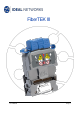
FiberTEK III FiberTEK III User Manual Document 164802 Iss 3 Page 1
COPYRIGHT NOTICE The information contained in this document is the property of IDEAL INDUSTRIES Ltd. and is supplied without liability for errors and omissions. No part of this document may be reproduced or used except as authorized by contract or other written permission from IDEAL INDUSTRIES Ltd. The copyright and all restrictions on reproduction and use apply to all media in which this information may be placed. IDEAL INDUSTRIES Ltd.
Safety Precautions WARNING! NEVER look directly into the port of measuring adapter, at connector surface, open fiber ends or into couplers. There is a risk of light emerging from the fiber that is not visible, which could permanently damage your eyes. If you are not sure whether the device is switched on or whether the fiber transmits light, for safety reasons always assume that the device is active. Handle bare fibers properly; there is a risk of injury from fiber splinters.
Information on the use of this Instruction Manual The following symbols used in this manual indicate that the user should exercise particular caution in order to prevent personal injury or damage to the FiberTEK™ III or the system under test. WARNING! This symbol indicates potentially lethal voltages or dangerous situations. The life and/or health of the person performing the activity or anybody in the vicinity is at risk.
CONTENTS Chapter 1. Specifications ..........................................................................................................................6 Chapter 2. Product Description .............................................................................................................. 10 2.1 Test Modules ............................................................................................................................ 10 2.1.1 Controls, Ports, Indicators and Connectors ..............
Chapter 1. Specifications Testing speed 1. At 23 ±1 ºC unless otherwise specified. 2. After ten-minute warm-up time. Autotest 8 seconds for each fiber / fiber pair (i.e. twice this for a Bi-Directional test) Input (Meter) connectors Universal with adaptors for FC, ST, SC and LC Output (Source) connectors Universal with adaptors for FC, ST, SC and LC Fiber type 9/125 μm, 50/125 μm and 62.
Display update rate FiberTEK III User Manual 10.0 to 99.9 uW 100 to 999 uW Length: 0.1m / 0.
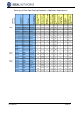
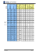
ISO 11801 Generic Cabling ISO 11801 Generic Cabling Max Splice Insertion Loss (dB) Min Connector Return Loss (dB) Maximum Distance (m) Min Operating Distance (m) (50um/62.5um) Max Fiber Attenuation (dB/km) Min Fiber Bandwidth (MHzkm) Core size (um) / wavelength (nm) 62.5/850 50/850 62.5/1300 50/1300 62.5/850 50/850 62.5/1300 50/1300 Max Connector Insertion Loss (dB) Multimode Multimode Multimode Multimode Multimode Multimode Multimode Multimode Max Link Channel Loss (dB) TIA 568-B.
3.25 OF-500 OM3 2.25 OF-500 OS1 OF-2000 OM1 OF-2000 OM1 OF-2000 OM2 OF-2000 OM2 50/130 9/1310 or 1550 50 or 62.5/850 50 or 62.5/1300 50 or 62.5/850 50 or 62.5/1300 OF-2000 OM3 50/850 8.50 OF-2000 OM3 4.50 OF-2000 OS1 Multimode/ OM1-OM2 Multimode/ OM1-OM3 Multimode/ OM1-OM3 Multimode/ OM1-OM2 Multimode/ OM2-OM3 Multimode/ OM1-OM3 Multimode/ OM2-OM3 Multimode/ OM1-OM2 Multimode/ OM1-OM2 Singlemode/ OS1 MultimodeOM1 MultimodeOM1 Multimode/ OM2-OM3 50/130 9/1310 or 1550 62.5/850 12.
Chapter 2. 2.1 Product Description Test Modules FiberTEK™ III is a fiber optic adaptor module for the IDEAL LanTEK III Cable Certifier. .It is available as either Single-mode (SM) module or a Multimode (MM) module and may be used either singly in “looped” mode with LanTEK III Display handset or as a pair also using the Remote handset. NOTE Many of the generic functions of LanTEK III, such as Power, Jobs Management and Talk Mode, are available when FiberTEK™ III is in use.
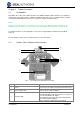
FiberTEK™ III adaptor and communications between adaptor(s) established Note: This LED is useful for identifying which fiber is which in a duplex cable. It is not necessary to plug the fiber into the Rx Port to do this - bringing the fiber end near to the Rx Port is sufficient. Always keep in place when the ports are not in use to protect against damage and dust. 4 Protective caps 5 System connector 6 Red light source 7 Tx Port Connection to LanTEK III Visible source for cable identification. 2.
Tx LC Adaptor (optional) Fig. 2 Fiber Adapters LC adapters are available optionally. The correct LC adapter must be used on the Tx Port - MM (Orange boot- part number 025202) / SM (Yellow boot - part number 025201). When using LC adapters, the adapter ring must first be removed from the Rx Port. To remove an adapter, unscrew it anticlockwise. Before fitting the new adapter, clean the inside of the ferrules in the port connector and in the adapter with a cotton bud.
Chapter 3. Calibration To comply with precision requirements, you should have your LanTEK III and FiberTEK™ III Cable Tester calibrated on an annual basis. Before sending the tester for calibration or maintenance, please contact the local Technical Customer Service of IDEAL INDUSTRIES at www.idealnetworks.net 3.1 Field Calibration During calibration, FiberTEK™ III calculates a reference level for the loss measurement.
Fig. 3 One Jumper Field Calibration If it is not possible or practical to plug the cable under test directly into the Rx Port (for example if it is a Permanent Link) the 3-Jumper test method must be used instead. For Field calibration in this method, 3 jumpers are used in each direction - a Launch Cord, a Field Calibration Cord and a Tail Cord. Fig. 4 Three Jumper Field Calibration For testing cables where both ends are available in one location, a Loopback method is provided.
Fig. 6 Loopback Field Calibration (3-Jumper) Use the soft keys / to select whether to test a single cable in one direction or a duplex cable in both directions. (This setting does not affect the Field calibration.) 5. Use soft key to start the Field Calibration 6. Follow the instructions on screen 7. After the Field Calibration is complete, an indication of the quality of the jumper(s) used is shown: Fig.
Chapter 4. Testing using FiberTEK™ III All cable parameter default settings programmed in the FiberTEK™ III Cable Certifier are based on generic standards, proposed industry recommendations for cables and network links, the latest technical information available from International LAN cabling standards committees, the LAN industry, and IDEAL INDUSTRIES' own experience and testing. Before performing any measurements, IDEAL INDUSTRIES, LTD.
The launch cord used for the field calibration must not be disconnected from the source otherwise the calibration is invalid. PM LS Launch cord Measured Loss LS PM Launch cord Fig. 9 4.3 Link under test Test Setup According to Reference Method with One Test Cord Set Autotest Pref Autotest is the test mode used most often. The Autotest allows various presettings: Automatic saving Passed/Failed Rating 1. On start screen of Display handset (DH) select option Preferences. 2.
Fig. 10 Select fiber type 4.3.2 Selection of Refractive Index 1. Use Arrow Keys to navigate on ready screen to " LASER" display and confirm with Enter. 2. Use soft key to display the Refractive Index screen. 3. Set the Refractive Index according to the cable manufacturer's data. Note: The Refractive Index setting is not affected by changing the Fiber Standard Fig. 11 Set refractive index 4.3.3 Selection of Fiber size and Wavelength 1.
4.3.4 Determine Loss Budget The loss budget influences the passed/failed thresholds for the loss measurements performed with FiberTEK™ III. However, since the loss budget has no impact on the actual loss measurement, this function is for informative purposes only. If the measured loss is smaller or equal to the loss budget, a is displayed. If the loss exceeds the loss budget, the following symbol appears: Use soft key . to open Loss Budget Menu and to change limits according to wavelength. Fig.
2. Use soft key to calculate the budget. The result appears in Loss Budget box. 3. To confirm, press Enter in this box and press Enter in the next box. 4. Return to the Main Menu by pressing Enter once more. The new limits will now be used when an Autotest is performed. 4.4 Evaluation of Autotest Results for Fibers (LWL) 4.4.1 Passed/Failed Rating The overall Autotest result appears in the upper right of the Autotest screen.
4.4.4 Working with Jobs The Autotest is saved under an unique name. The test results can be viewed, printed or deleted on the File screen. 1. On the ready screen, select File option and open job list. 2. Mark the desired job. Use to open the folder containing the option list. 3. Mark the desired function and confirm with Enter. 4.4.5 Display of Result Details The Autotest is saved under an unmistakable name. The test results can be viewed, printed or deleted on the File screen. 1.
Chapter 5. FiberTEK™ III Analyse Mode The FiberTEK™ III selects the reference level and test limits based on the test selected. When testing fibers (LWL), the remote handset (RH) must be manually powered on. 1. Set the cable parameters including the wavelength, and perform a field Calibration if necessary. 2. On the ready screen, select Analyse. Fig. 15 Analyze 5.1.1 Continuous Run This mode is used for troubleshooting. During continuous run, the measurement is repeated until it is manually cancelled.
Fig. 17 Continuous Running The FiberTEK™ III makes a measurement every few seconds. Each time a measurement is made a beep is heard and the results shown on the screen are updated. Use soft key Once stopped, the result can be saved using soft key 5.1.2 to stop the test. . Power Meter Mode The FiberTEK™ III can be used as a power meter to measure the optical power received from a source. 1. In the Analyze screen select Power Meter. Fig. 18 Power Meter 2.
8. Use soft key in dBm.