
Product Manual

2
Apr. 2020-1
WHLSTDKIT-UF-2500EH-X
Safety Information:
· DO NOT OVERLOAD WHEEL STANDS. THE CAPACITY OF EACH WHEEL STAND IS SHOWN ON
COVER OF THIS DOCUMENT AND/OR ON THE SIDE OF WHEEL STANDS.
· POSITIONING THE VEHICLE IS VERY IMPORTANT. ONLY TRAINED TECHNICIANS SHOULD
POSITION THE VEHICLE ON WHEEL STANDS.
· ALWAYS INSERT ALL LOCK PINS TO STAND PILLARS, TO SECURE STAND HEIGHT IN PLACE.
· AVOID EXCESSIVE ROCKING OF THE VEHICLE WHEN SUPPORTED ON LIFT OR WHEEL STANDS.
· ONLY USE ON A FLAT LEVEL CONCRETE SURFACE WITH A RECOMMENDED MINIMUM
THICKNESS OF 4”. NOT RECOMMENDED FOR USE ON AN ASPHALT SURFACE.
· MAINTAIN A SAFE DISTANCE FROM LIFT & WHEEL STANDS WHEN LOADING OR UNLOADING.
POWER SPORT VEHICLES ‘ON OR OFF’ WHEEL STANDS OR LIFT.
· UNAUTHORIZED PERSONNEL SHOULD NEVER BE IN THE SHOP AREA WHEN WHEEL STANDS OR
LIFT ARE IN USE.
· INSPECT THE WHEEL STANDS DAILY. THE WHEEL STANDS SHOULD NEVER BE USED IF THEY
HAVE DAMAGED COMPONENTS OR IF MALFUNCTIONING. ONLY QUALIFIED TECHNICIANS
SHOULD SERVICE THE WHEEL STANDS.
· REPLACE DAMAGED COMPONENTS WITH MANUFACTURER’S PARTS, OR EQUIVALENT.
· KEEP THE AREA AROUND THE WHEEL STANDS CLEAR OF OBSTACLES.
Specifications:
Assembly: (Note: Some components may already be pre-assembled.)
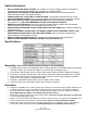
1. Carefully remove items from shipping crate to ensure all parts are included using the Exploded
Drawing & Parts List. Contact the Dealer for any missing or damaged parts.
2. Insert upper Tube Frames (#2) into lower Tube Frames (#8) as shown in Exploded Drawing.
3. Connect Cross Brace (#3) to lower Tube Frames, using the hardware provided (#11,12 & 14).
4. Place Wheel Platform (#1) on top of upper Tube Frames & secure with hardware provided
(#18, 20 & 21) as shown in Exploded Drawings.
5. If applies, install Plastic Caps (#19) to ends of upper Tube Frames.
6. Check for any loose connections, tighten bolts & nuts as required.
Operation:
· Using the UF-2500EH-X Lift, raise the power sport vehicle to the desired working height and lower onto
mechanical latches, using the Operational & Safety procedures noted in the UF-2500EH-X Manual.
· Once the power sport vehicle is secured at the desired lifting height, remove all Cotter & Lock Pins to
adjust Wheel Stands heights to be slightly lower than the wheels.
· Ensuring the adjusted height is the same for all Stands, insert ALL Lock & Cotter Pins for each Pillar
to secure Wheel Platforms in place.
· Position & center the Wheel Stands directly under the vehicle wheels, then lower the UF-2500EH-X Lift
until the Wheel Stands fully supports vehicle’s weight. Check for vehicle stability on Stands.
· Reverse the above operation to place vehicle’s weight back on UF-2500EH-X Lift, to remove Wheel
Stands from under Power Sport Vehicle. Remove Stands prior to lowering vehicle with Lift.