
Instruction Manual


I C R E A L T I M E S E C U R I T Y S O L U T I O N S
8
Using the included hex wrench from the accessories kit, unfasten the 3 hex screws on the
dome camera enclosure and then remove it.
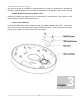
• Step 2: Place mounting template
Included with the camera is a mounting template that can be adhered to the target
installation surface for ease of installation. Following the diagram, bore 3 small holes as
indicated on the diagram, around the perimeter of the template. Once you‟ve created your
holes, insert the plastic anchors securely and firmly.
If you need to pass the cameras cable through the mounting plate, be sure to bore out the
template area marked „Cable Exit‟ to allow for the female RJ-45 plug to pass through.
If you need to pass the cameras cable through the side of the cameras enclosure, be sure to
snip out the Ushape knock out in order to allow the cable a wire path.
• Step 3: Mount camera base
Adjust the cameras base plate, and pull the cable through your exit hole. Match the ”TOP”
direction of the camera with that from the installation template. Align the 3 base plate holes
with the plastic anchors from Step 2. Using (3) ST3.0 self tapping screws from the
accessories kit, fix the camera base plate onto the installation surface by screwing the ST3.0
screws through the holes, and into the plastic anchors.
• Step 4: Replace dome cover
Lastly, take the dome cover and align it with the base plate that is now fixed to the
installation surface. Using the hex key from step 1, replace the 3 hex screws, securing the
dome back in place.
Note: If connect the host GND to ground lead, may improve device reliability. The GND locates next to exit hole on the rear side of
the chassis and the GND screw is M3.
2.c SD Card Installation
• Step 1: Disconnect power source from the IP Camera