
Installation guide


_ Installation Instructions Blower Cabinet I
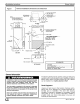
5. Connect low-voltage leads to thermostat and
outdoor unit. See Fig. 5 and 6 and the outdoor unit
wiring label.
Use No. 18 AWG color-coded, insulated (35°C minimum)
wire to make low-voltage connections between thermostat
and unit. If thermostat is located more than 100 ft from unit
as measured along low-voltage wire, use No. 16 AWG
color-coded, insulated (35°C minimum) wire. All control
kits from the factory utilize a printed-circuit board (PCB)
which has a low voltage circuit protective fuse (5 amp), fan
motor speed tap selection terminal (SPT), and time delay
relay (TDR) jumper. To disable the TDR feature, sever the
jumper wire JWl.
Electrical shock hazard.
Unit cabinet must have a continuous electrical
path to ground in order to minimize potential for
personal injury or death if an electrical fault
should occur. This ground may consist of electri-
cal wire or approved conduit when installed in ac-
cordance with existing codes.
Failure to do so can result in property damage,
personal injury and/or death.
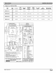
See Figure 8 for Cooling Control and heater package part
numbers, wire size, overcurrent protection sizes. All
field-installed cooling control kits and heater packages are
factory wired for 230-v transformer operation. When
208-v transformer operation is desired, move the black
primary lead from the 230-v terminal to the 208-v terminal.
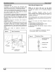
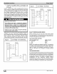
Figure 6 Low Voltage - Air Conditioning
THERMOSTAT
FAN COIL
(CONTROL)
R
G
_ w2
AIR COND.
Figure 7 Low Voltage - Heat Pump
THERMOSTAT
[]
[]
FAN COIL
(CONTROL)
VlO W2
HEAT PUMP
(CONTROL)
4Q_ R
fi:3_c
W2
4:::%0
fi: _y
A98331
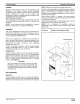
SELECT PROPER BLOWERSPEED
Before operating unit, be sure that proper blower speed
has been selected. High speed tap is recommended for
most applications. For those applications requiring lower
air flows, low speed tap can be used.
ColorCodeForMotorLeadWires
MOTOR SPEED TAP WIRE COLOR
C - Common Yellow
1 - High Black
2 - Low Red
NOTE: Fan speeds are selected manually. To change the
fan speed, interchange the black and red fan motor leads
on printed circuit board terminal SPT (COM). START-UP
Refer to outdoor unit Installation Instructions for system
start-up instructions and refrigerant charging method
details.
CAREAND MAINTENANCE
For continuing high performance and to minimize possible
equipment failure, it is essential that periodic maintenance
be performed on this equipment. Consult your local dealer
as to proper frequency of maintenance and availability of a
maintenance contract. The ability to properly perform
maintenance on this equipment requires certain
mechanical skills and tools. If you do not possess these,
contact your dealer for maintenance. The only consumer
service recommended or required is filter maintenance.
_J 664 01 3001 00