
Installation guide


I Blower Cabinet
FieldInstallation of Controls
Units shipped from factory without heaters require a
field-installed cooling control kit or heater. These kits are
completely assembled and factory-wired for easy
installation.
See Installation Instructions packaged with heaters for
installation procedures. These unit Installation Instructions
are to be used in conjunction with instructions packaged
with heater. When installing accessory heat, optional
cooling control kit is not required.
INSTALLCOOLINGCONTROLPACKAGE
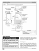
1. Remove blower access panel (See Fig. 5.)
2. Install cooling control panel above blower motor on
blower side plate. Attach with provided screws. (See
Fig. 5.)
3. Route thermostat leads through small knockout in top
of unit. Use grommet provided with cooling control to
protect leads where they pass through casing.
4. Make low-voltage splice connections in low-voltage
control box.
5. Route blower motor power leads up through hole in
bottom of cooling control. Connect yellow common
wire to piggyback common terminal on transformer.
Connect black (HI) or red (LOW) speed tap wire to
control board relay common terminal. See wiring
label for proper speed tap selection.
6. Route unit power supply through knockout in top of
unit and connect to line side of disconnect. Connect
ground wire to ground lug. See wiring label to make
connections.
7. Remove disconnect pullout.
8. Replace access panel.
ELECTRICAL CONNECTIONS
Electrical shock hazard.
Before installing or servicing fan coil, always turn
off all power to unit. There may be more than 1 dis-
connect switch. Turn off accessory heater power
if applicable.
Field wires on side of disconnect found in fan coil
remain live, even when pull-out is removed. Ser-
vice and maintenance to incoming wiring can not
be performed until main disconnect switch (re-
mote to the unit) is turned off.
Failure to do so can result in property damage,
personal injury and/or death.
NOTE: Before proceeding with electrical connections,
make certain that voltage, frequency, and phase
correspond to that specified on rating plate. Also, check to
be sure that the service provided by utility is sufficient to
handle additional load imposed by this equipment. Refer to
unit wiring label for proper field high- and low-voltage
wiring. Make all electrical connections in accordance with
Installation Instructions
9, Insert disconnect pullout through hole in access
panel,
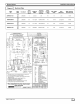
Figure 5 Cooling Control Kit
Ag8333
NOTE: Top panel not shown for ciarity
BLOWER
ACCESS UNIT
DOOR
A98335
NEC and any local codes or ordinances that might apply.
Unit must have a separate branch electrical circuit. The
Cooling Control Kit and the heater packages provide a
disconnect switch located within sight and readily
accessible to the unit.
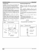
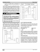
NOTE: All control kits are shipped from factory wired for
230-v transformer operation. For 208-v operation, move
black primary lead from 230-v terminal to 208-v terminal.
See Fig. 6 and 7 for field low-voltage wiring. See Fig. 1 for
location of the electrical inlets. For maximum ampacity and
over-current protection, see unit rating plate.
1. Provide power supply for unit being installed in
accordance with unit wiring diagram and rating plate.
2,
3,
4,
Connect line-voltage leads to field lugs, Use copper
wire only.
Use UL listed conduit and conduit connector for
connecting line-voltage leads to unit and obtaining
proper ground. Grounding can also be accomplished
by using the ground lug provided in the control box.
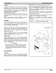
Install rubber grommet packed with unit in hole for
low-voltage wires.
664 01 3001 O0 5L_