
Installation guide


_ Installation Instructions Blower Cabinet I
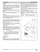
Condensate Drain
Condensate pan has primary and secondary drain
connections to meet FHA requirements. (See Fig. 3.)
These connections have 3/4-in. female pipe threads.
Tubing for all condensate drains should be a minimum of
7/8-in. OD. Drain lines from condensate pan to exterior of
unit must be plastic pipe. Drain should be pitched
downward at a slope of 1 in. per 10 ft.
If coil is located in or above a living space where damage
may result from condensate overflow, a separate 3/4-in.
drain must be provided from secondary drain connection.
Run this drain to a place in compliance with local
installation codes where it will be noticed when unit is
operational.
Condensate flowing from secondary drain indicates a
plugged primary drain.
Install a 3-in. trap in condensate drain line as close to coil
as possible. Make sure that the top of trap is below
connection to drain pan to prevent condensate from
overflowing drain pan. Prime trap with water. Insulate drain
if located above a living area and test condensate line for
leaks.
Consult local codes for additional restrictions or
)recautions.
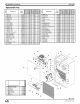
Figure 3 Drain Connections
/
/
/
/
/
DRAIN EXIT
PRIMARY
DRAIN
SECONDARY
DRAIN
(TRAP EXTERNAL
TO UNIT)
NOTE: Use plastic pipe from
condensate pan to
exterior of fan coil.
A86005
Orifice Sizing & Refrigerant Lines
NOTE: Do not remove seals from coil until tubing
connections are ready to be made. See instructions
packaged with outdoor unit for connecting refrigerant
tubes.
Before connecting refrigerant tubing, be sure
factory-supplied indoor refrigerant flow-control device is
correct for outdoor unit size used. Refer to outdoor unit
installation instructions.
When changing piston, use a backup wrench and do not
over tighten. Maximum torque should not exceed 30 ft-lb.
(See Fig. 3.)
Move unit into place and install refrigerant tubing as
follows:
1. Route tubing to connection points.
2. Remove plugs from liquid and suction tubes.
3. Clean and braze tubing into place.
4. Pressurize system and leak-test. Repeat procedure
until leak-free.
CAUTION
Do not vent refrigerant to atmosphere. Recover
during system repair or final unit disposal.
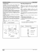
Figure 4 Restrictor Orifice
Nut and Liquid Line
_-_ Rounded End
__ Feeder Tubes
_J 664 01 3001 00