
Installation guide


I Blower Cabinet
Location
Select the best position which suits the installation site
conditions. The location should provide adequate
structural support, space in the front of the unit for service
access, clearance for return air and supply duct
connections, space for refrigerant piping connections and
condensate drain line connections.
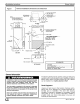
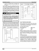
See Clearances in Figure 1.
A front access panel is provided, which permits access to
blower assembly and electrical controls for removal and
servicing.
NOTE: Local codes may limit application of systems
without a ducted return to single story dwellings.
Installation
The unit is designed for free-air return as enclosed in a
closet with Iouvered door or for flush mounting in a wall. A
factory-authorized Iouvered grille kit is available for flush
mount application (AMWK001WG).
When unit is installed in a closet with a Iouvered door in
return-air path, the free area of Iouvered opening in the
door must be a minimum of 2.25 sq ft. Either align door
opening with unit inlet or provide a l O-in. clearance
between door and unit.
If unit is to be flush mounted in a wall, provide adequate
support underneath base of unit. To assure proper
condensate drainage, be sure unit is level.
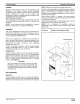
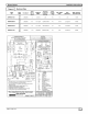
HangingCabinet
Cabinet may by hung from the wall using accessory
brackets (AMWK001MK). Use 1X 4 or 2 X 4 support and a
spacer for the bottom across studs to support the unit.
Bottom spacer should be located above the bottom of the
unit so it holds the unit out from the wall in a vertical
position, See Figure 2,
CAUTION
Both wall support and spacer must be the same
thickness or the unit will not hang correctly and
Condensate Water will not drain correctly. Unit must
be vertical or tilted slightly forward which the support
bracket will do.
Duct Connections
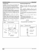
SupplyDuct
Connect supply-air duct over 3/4-in. flange provided on
supply-air opening. Secure duct to flange using applicable
fasteners for type of duct used, and seal duct-to-unit joint.
Installation Instructions
NOTE: Short duct runs tend to increase noise level.
When fan coil is equipped with an electric heater, install air
ducts in accordance with standards 90A and 90B of
National Fire Protection Association (NFPA). Use of
flexible connectors between ductwork and unit will prevent
transmission of vibration.
When electric heater is installed, use heat-resistant
material for a flexible connector between ductwork and unit
air discharge connection.
Ductwork passing through unconditioned space must be
insulated and covered with a vapor barrier.
NOTE: Unit is intended for nonducted return-air
applications. Local codes may limit this unit to single-level
applications.
Figure 2 Attach Coil Cabinet to Wall
Support Brackets
664 01 3001 00 3L_ J