
Installation guide


I Installation Instructions Blower Cabinet I
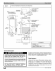
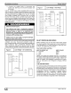
Figure 1 Nominal Installation Dimensions and Clearances
REFRIGERANT
LINESENTRY
NOTE:
1. SERIESDESIGNATIONIS
THE 14THPOSITION
OF UNITMODELNUMBER.
38 1/'16 I
241/16
_/_ LOWVOLTAGEENTRY
(`'/8 DIA. ROLE)
POWERENTRY
:L'J/8DIA. KNOCKOUT
"/8 DIA.HOLE
2 1_16
•_,-_ 9/16
i-<--
@
BLOWER,CONTROLAND
ELECTRICHEATER
ACCESSPANEL
LIQUIDTUBE
UNITCONNECTIONSIZES
SUCTION3/4I.D. SWEAT
LIQUID,3_ I.D._WEAT
CONDENSATE,_/4 NPT
,-- FILTERMEDIA
-- SECONDARYDRAIN
1_16
I-- PRIMARY DRAIN J -,-97/16--
-4-11 1/16-=-
FRONTVIEW
_-11 1/16-----1_[
PATCHPLATE ._L_ 5
FANCOILBASE #
BOTTOMVIEW
CLEARANCES
All Sides .................................. 0"
From Supply Duct .......................... O"
Recommended Service From Front .......... 21"
(Service for blower, filter)
GeneralInformation
Installation or repairs made by unqualified persons can
result in hazards to you and others. Installation MUST
conform with local building codes and with the
National Electrical Code NFPA70 current edition.
The information contained in this manual is intended
for use by a qualified service technician familiar with
safety procedures and equipped with the proper tools
and test instruments.
Failure to carefully read and follow all instructions in
this manual can result in equipment malfunction,
property damage, personal injury and/or death.
The blower cabinet may be used for cooling or heat pump
operation with or without electric heat. Installations without
electric heat, require a Cooling Control Kit. The cabinet
can be installed in an Upflow position ONLY.
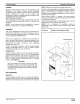
Check Equipment
Unpack unit and move to final location. Remove carton,
taking care not to damage unit. Inspect equipment for
damage prior to installation. File claim with shipping
company if shipment is damaged or incomplete. Locate
rating plate on unit. It contains information needed to
properly install unit. Check rating plate to be sure unit
matches job specifications.
_J 664 01 3001 O0