
Installation guide

_ Installation Instructions Fan Coils]
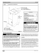
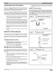
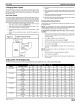
FigUre ! Dimensions and Clearances
14-3/8" (2-2 1/2 Ton)
17-7/8" (3-3 1/2 Ton)
21-1/2" (4 Ton FCP Only)
25-1/8" (5 Ton) (4 Ton FCX Only)
Filter Door
16-3/8" (2-2 1/2 Ton)
19-7/8" (3-3 1/2 Ton)
23-1/2" (4 Ton FCP Only)
27-1/8" (5 Ton) (4 Ton FCX Only)
8 1/2"
2"
42"
(2-3 1/2 Ton)
52"
(4-5 Ton)
21 1/2"
38-20-17
CLEARANCES
NO HEATERS
All Sides .................................. 0"
From Supply Duct .......................... 0"
Recommended Service From Front .......... 20"
(Service for blower, filter if installed)
WITH HEATERS
All Sides .................................. 0"
From First Three
Feet of Supply Duct to Combustibles ........ 1"
From Duct after Three Feet ................. 0"
Recommended Service From Front .......... 20"
(Service for blower, filter, heaters if installed)
Fire Hazard
When heaters are installed maintain clear-
ances from combustible materials as speci-
fied on unit rating plate. Do not use plastic
lined or combustible flexible ducting within 36
inches of the supply end of the air handler.
Failure to do so can result in fire, property
damage, personal injury and/or death.
General Information
Installation or repairs made by unqualified persons can
result in hazards to you and others. Installation MUST
conform with local building codes and with the
National Electrical Code NFPA70 current edition.
The information contained in this manual is intended
for use by a qualified service technician familiar with
safety procedures and equipped with the proper tools
and test instruments.
Failure to carefully read and follow all instructions in
this manual can result in equipment malfunction,
property damage, personal injury and/or death.
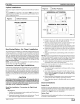
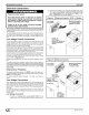
The blower cabinet may be used for cooling or heat pump opera-
tion with or without electric heat. Installations without electric
heat, require a No Heat Kit.The cabinet can be installed in an up-
flow or horizontal position (Figure 2, 3). Horizontal installations
require a horizontal kit. Some models are shipped with the hori-
zontal kit already installed .These units are not shipped with air fil-
ters installed. Filter must be field supplied, either washable or
disposal type. Washable filters are available as an accessory.
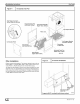
Location
Select the best position which suits the installation site conditions.
The location should provide adequate structural support, space in
the front of the unit for service access, clearance for return air and
supply duct connections, space for refrigerant piping connections
and condensate drain line connections. If heaters are being
installed make sure adequate clearance is maintained from sup-
ply ductwork, See Clearances and Warning in Figure 1.
NOTE: Internal filter can be accessed from separate filter door. If
the filter can NOT be easily accessed, a remote filter is recom-
mended. Refer to ACCA Manual D for remote filter sizing.
Ifthe unit is located in an area of high humidity, nuisance sweating
of casing may occur. On these installations a wrap of 2" fiberglass
insulation with a vapor barrier should be used.
_J 49601 4111 03