
Installation guide

I Fan Coils Installation Instructions
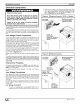
Changing Motor Speed
The blower motor comes from the factory wired for high or Med
speed. To change the blower speed, disconnect the black wire at
the blower motor terminal block and reconnect at the desired
blower speed tap.
Air Flow Check
For proper system operation, the air flow through the indoor coil
should be between 350 and 450 cfm per ton of cooling capacity.
The air flow through the unit can be determined by measuring the
external static pressure to the unit and selecting the motor speed
tap that will most closely provide the required air flow.
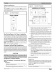
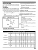
1. Set up to measure external static pressure at the supply
and return duct connections (Figure 13).
2. Drill holes in the ducts for pressure taps, pitot tubes, or oth-
er accurate pressure sensing devices.
3. Connect these taps to a level inclined manometer or draft
gauge.
4. Ensure the coil and filter are clean, and all the registers are
open.
Figure 13 Static Pressure Check
SupplYr____
e °on
5. Determine the external static pressure with the blower op-
erating.
6. Refer to the Air Flow Data tables, page 9 to find the speed
tap that will most closely provide the required air flow for the
system.
7. Refer to Changing the Motor Speed in these instructions if
the speed tap is to be changed.
8. Recheck the external static pressure with the new speed
tap, and confirm speed tap selection.
Temperature Rise Check
Temperature rise is the difference between the supply and return
air temperatures.
NOTE: The temperature rise can be adjusted by changing the
heating speed tap at the unit's blower terminal block. Refer to the
unit's Installation Instructions for airflow information.
A temperature rise greater than 60°F (33.3°C) is not recom-
mended.
1. To check the temperature rise through the unit, place ther-
mometers in the supply and return air ducts as close to the
unit as possible.
2. Open ALL registers and duct dampers.
3. Set thermostat Heat-Cool selector to NEAT.
4. Set the thermostat temperature setting as high as it wil! go.
5. Turn electric power ON.
6. Operate unit AT LEAST 5 minutes, then check tempera-
ture rise.
NOTE: The maximum outlet air temperature for all models is
200°F (93.3°C).
7. Set thermostat to normal temperature setting.
8. Turn electric power OFF
9. Be sure to seal all holes in ducts if any were created during
this process.
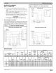
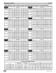
Airflow220V/ 50 Hz Models0nly
NOTES: Performance based on unit with horizontal drain pan installed, dry coil, no filter, Deduct Filter Static
MODEL BLOWER SPEED 0.1 0.2 0.3 0.4 0.5
FCP2400D HIGH 885 825 723 643 499 297
MEDIUM 873 811 708 573 380 266
LOW 775 728 645 558 416 188
FCP3000D HIGH 1,225 1,175 1,067 1,031 891 794
MEDIUM 1,160 1,115 1,014 980 847 747
LOW 1,034 1,001 919 886 765 667
FCP3600D HIGH 1,384 1,328 1,206 1,165 1,007 897
M EDIUM 1,311 1,260 1,146 1,107 957 844
LOW 1,168 1,131 1,038 1,002 865 754
FCP4200D HIGH 1,578 1,527 1,399 1,338 1,143 964
MEDIUM 1,446 1,402 1,288 1,224 1,037 876
LOW 1,198 1,184 1,111 1,073 927 805
FCP4800D HIGH 1,657 1,603 1,469 1,405 1,200 1,012
MEDIUM 1,518 1,472 1,352 1,285 1,089 920
LOW 1,258 1,244 1,167 1,128 973 845
FCP6000D HIGH 1,960 1,902 1,748 1,702 1,485 1,317
MEDIUM 1,869 1,815 1,670 1,626 1,419 1,252
LOW 1,759 1,715 1,585 1,545 1,351 1,202
496 01 4111 03 9L_