
Installation guide

I Installation Instructions
Electrical Connections
Electrical shock hazard.
Turn OFF electric power at fuse box or service
panel before making any electrical connections
and ensure a proper ground connection is made
before connecting line voltage.
Failure to do so can result in property damage,
personal injury and/or death.
All electrical work MUST conform with the requirements of local
codes and ordinances and the National Electrical Code NFPA 70
current edition.
The low voltage transformer and the fan control are standard on
all models and are prewired at the factory. Line voltage connec-
tions are made to the heater accessory or the wire pigtails in the
unit.
Low Voltage Control Connections
The 24 volt power supply is provided by an internally wired low
voltage transformer which is standard on all models. If power
supply is 208 volt, the low voltage transformer must be rewired to
the 208 volt tap. See the unit wiring label.
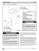
Field supplied low voltage wiring can enter the unit on the top left
hand corner or the left hand side panel. When using the left hand
side panel entrance, the low voltage wiring must be fed through
the entrance hole in the bottom of the control box.
Install the strain relief bushing (supplied with unit) in the selected
hole and a hole plug (supplied with unit) in the unused hole.
Connect the field wiring at the screw terminals of the control
board. Refer to Figures 9, 10.
Keep the low voltage wiring as short as possible inside the control
box.
Complete connections between indoor blower, outdoor section,
indoor thermostat and electronic outdoor thermostat (accessory)
according to instruction provided with the Condenser Installation
Instructions or those provided with the accessory and refer to Fig-
ures 11&12.
Overcurrent Protection
The power supply wiring to the unit MUST be provided with over-
current protection. Governing codes may require this to be fuses
ONLY or circuit breakers.
For blower cabinets without heaters, a 15 amp circuit may be
used.
Line Voltage Connections
Line voltage wiring may be brought into the unit through the top
right-hand corner or the right-hand side panel. The correct hole
size required by the conduit fitting must be punched at the pilot
hole location. Plug the unused pilot hole with a hole plug (supplied
with unit).
Connect field wiring to appropiate terminals on electric heater or
the wire pigtails. All line voltage connections must be made with
copper wire.
Line Voltage Connection
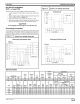
1. Provide line voltage power supply (208V-240V) from a
separate circuit(s). Size per table or table in heater manual.
Fan Coils I
2. Connect line voltage to the lugs with the Black and Yellow
wires, or to circuit breakers or wire leads from heaters. Re-
fer to Figure 9 for FCP--D Series and Figure 10 for
FCP--C and FOX and wiring diagram.
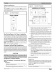
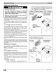
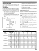
Figure 9 1 Electrical Controls - (FCP--D Series)
Low Voltage Matching Receptable
Connections For Electric Heater
(Unplug Connector)
Pigtails for
Line Voltage
(Yellow and Black) and
Ground Connection
en)
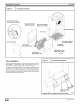
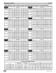
Figure 10 I Electrical Controls
Low Voltage
Connections
Matching Receptable
For No Heat Kit
or Electric Heater
Filler Plate
(FCP/X48-60)
Flanges Together
Adapter Plate
(FCP36-42, FCX36)_
No Heat Kit
Lugs for
Line Voltage
and Ground
Connections
_J 49601 4111 03