
Manual

User's Information Manual
CirculatingAir Blower
The blower circulates room air through the furnace, air ducts, and
into the rooms of the structure. The blower can be set at the ther-
mostat for automatic or manual operation. In manual mode the
blower operates continuously. In automatic, the blower does not
come on until a preset time after the gas valve is energized. When
the structure reaches the temperature set on the thermostat, the
furnace will shut off. The blower will continue to run until the fur-
nace cools down.
Thermostat
There are many types and styles of thermostats. Most thermo-
stats control both heating and cooling functions and have a Fan
Switch with AUTO and ON settings. On AUTO, the Circulating Air
Blower will cycle on/off with the furnace on the heating speed un-
less a call for cooling is initiated. Blower speed will correspond to
the mode of operation of the furnace. If the Fan Switch is posi-
tioned to ON the blower will run continuously.
In addition some thermostats are programmable with multiple set
backs. The set backs can be pre-programmed to lower or raise
the temperature automatically.
Be sure to become familiar with your thermostat,
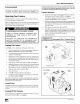
Rating Plate
The rating plate contains important information for the service
technician and lists the complete model, manufacturing and serial
numbers. You should always provide all these numbers when re-
questing parts or if you need service. See Figure 4, Figure 5, or
Figure 6 for rating plate location.
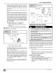
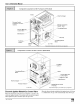
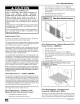
iiii I c°mP°nent L°cati°ns f°r F°ur P°siti°n 90+ Furnaces
Furnace Vent Pipe (Vent Pipe Connections Air Intake Pipe
through Side Panel on Some Models (Required only for Direct-Vent Furnaces)
Manual Equipment Shutoff Valve
Vent Pipe Grommet
Diagnostic
Primary Heat Exchanger
Vent Drain
Combustion Blower
1/2" I.D. Vent Pi
5/8" I.D. Transition
Furnace Main Gas Control Valve
Secondary
Heat Exchanger
Pressure Switches
(some models have one)
Door Interlock Switch
Condensate Tra I
Plastic Transition Box
Circulating Air Blower
Fan/Delay Rating Plate
Representative drawing only, some models may vary in appearance,
Door Interlock Switch
All the electrical power for the furnace goes through the door inter-
lock switch. The interlock switch interrupts electrical power to the
furnace when the blower door is removed. The furnace will not op-
erate until the blower door is reinstalled.
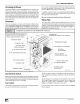
Fan Control
The fan/delay control provides power to the circulating air blower
to keep it on until the furnace cools down.
D C Motor Control
(some models)
25-24-10-1
The fan off-delay setting can be adjusted if the fan remains on
long enough that cool drafts are felt in the room after the furnace
shuts off.
The off-delay is set by moving a set of switches on the control.
The Wiring Diagram located on the inside of the blower door
shows the various delay combinations. Refer to Figure 4,
Figure 5, or Figure 6 for location of the control.
If you are unsure how to set the Fan Control, contact a Qualified
Service Agency.
441 02 2010 04