
Manual


User's Information Manual
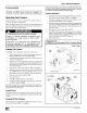
External Filter Rack
A plastic end cap is inserted in the filter rack after the filter is
installed. The end cap keeps air from escaping around the
open end of the filter rack. See Figure 8 for removal of filter.
Filter racks attached to the furnace are made so the filter simply
slides out one end for removal.
1. Turn OFF electric power to furnace.
2. Remove the end cap from the filter rack.
3. Slide the filter out of the filter rack.
4. Inspect the filter(s) and replace or clean washable types. If
filter is aluminum mesh it should be recoated with filter coat-
ing spray.
5. Reinstall the end cap in the filter rack.
6. Turn furnace on.
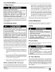
Internally Mounted Filter
1. Turn OFF power to furnace.
2. Remove blower door.
3. Slide filter straight out toward you. (See Figure 9.)
4. Inspect the filter(s) and replace or clean washable types. If
filter is aluminum mesh it should be recoated with filter coat-
ing spray.
5. Replace blower door
6. Turn on electric power to furnace.
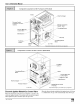
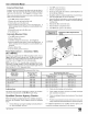
Filter Replacement -- Downflow _8DNL
(Not *8MPN/L)
Two filters are supplied with all '8DNL downflow models. (See to
Figure 10) Refer to note for proper size. The filters are installed
through the top of the downflow furnace from the right side. To re-
move filter, refer to Figure 10 for the following steps.
NOTE: Two (2) 16" x 18" cleanable high-velocity filters are rec-
ommended. A _8DNL downflow furnace with airflow up to 1200
cfm is permitted to replace the 16" x 18" cleanable high-velocity
filters with two 16" x 18" dis )osable filters.
Recommended Filter Sizes
furnace Size
Heating Input
1000 x Btuh
5O
50, 75, and 100
50,75,100, and125
100 and 125
125
150
Lubrication
Nominal Air Flow
Cubic Feet
per Minute (CFM)
800-900
1100-1300
1300-1500
1500-1700
1900-2100
2300-2500
1. Turn OFF power to furnace.
2. Remove compartment door.
3. Reach up above right side of blower, and lift dirty filters out
of rack at top of furnace.
4. Straighten up filters and pull straight down at side of blower.
Pull out through right side of door opening.
5. Inspect the filter(s) and replace or clean washable types. If
filter is aluminum mesh, it should be recoated with filter
coating spray.
6. Reinstall the filters in the filter rack.
7. Reinstall blower compartment door.
8. Turn ON electric power to the furnace.
Left Side
Right Side
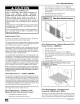
Downflow Filter Replacement
*8DNL
Recommended Filter Sizes
Sq. In, Surface Area/Nominal Size (inches)
Disposable Filters
500 or 20 x 25
350 or 14 x 25 (2Req.)
400 or 16 x 18 (2Req.)
500 or 20 x 25 (2 Req.)
600 or 20 x 30 (2 Req.)
600 or 20 x 30 (2 Req.)
Cleanable Filters
350 or 14 x 25
350 or 14 x 25
400 or16x18
500 or 20 x 25
500 or 20 x 25
720 or 24 x 30
The blower motor and the combustion air blower are prelubri-
cated by the manufacturer and DO NOT require oiling.
Qualified Service Agency Checks
When the furnace is being inspected for condition and opera-
tion have the Qualified Service Agency check the following
items.
1.
2.
3.
4.
5.
Check all flue gas passages including main and pilot burn-
ers, heat exchanger, and vent.
Check electrical wiring and connections.
Check supply and return air ducts for leakage, blockage
and connections to furnace.
Check circulating air blower wheel and motor. Clean them if
required.
Perform an operational checkout on the furnace to be sure
safety controls function and that furnace operates properly.
For additional information, the Qualified Service Agency can
consult the installation instructions for the furnace.
441 02 201004
25-21-16a