
Manual

User's Information Manual
RISK OF REDUCED FURNACE LIFE
Use of excessively dirty and/or restrictive air
filters may increase furnace operating
temperatures and shorten the life of the furnace.
Filters specified for the furnace are rated at a
maximum of 600 FPM air velocity and sized for the
furnace's airflow rate. Replacement filters must be of
equivalent type, size, and rating except as described
below.
Disposable, low-velocity filters may be used to replace
washable, high-velocity filters, providing they are sized
for 300 FPM or less.
If you are uncertain of the type of replacement filter to
use, consult the furnace installer or a qualified service
agency for assistance.
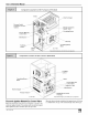
3. Slide the filter out of the filter rack. See Figure 8.
4. Inspect the filter(s) and replace or clean washable types. If
filter is aluminum mesh it should be recoated with filter
coating spray
5. Reinstall the end cap in the filter rack.
6. Turn on electric power to furnace.
Replacement Filters
If the filter is not located at or within the furnace, it should be lo-
cated somewhere in the return-air duct system.
The recommended sizes and types of filters that may be used with
your furnace are based on the furnace's heating gas input rate
(and cooling system capacity, if so equipped).
Replacement filters should be of the same type and size as the
original filters, to ensure adequate air flow and filtering. A dispos-
able low velocity filter can be replaced with a washable high veloc-
ity type. Do not replace a high velocity filter with a disposable low
velocity filter, except as permitted below.
If a cleanable (high-velocity) filter(s) is to be replaced with a dis-
posable (low-velocity) filter(s), the airflowarea of the filter(s) must
be doubled (i.e., a second filter of the same size must be installed
so that only half of the air goes through each filter). A second re-
turn-air duct to the furnace may be required in which to install the
second filter. Modification of a furnace installation shall comply
with the local installation code and the furnace installation instruc-
tions, and shall be made only by a Qualified Service Agency.
Filter Rack Outside Furnace
NOTE: Some filters are marked with an arrow to indicate the
proper direction of air flow through the filter. The air flow di-
rection will be towards the blower motor. Make sure filter is
installed correctly.
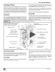
Filter Replacement - Upflow (*8MPN/L)
The filter may be installed inside the bottom of the furnace blower
compartment, or the filter(s) rack may be installed under the fur-
nace or on either or both sides of the furnace. A plastic end cap(s)
is inserted in the filter rack(s) after the filter(s) is installed. The end
ca p keeps air from esca ping around the open end of the filter rack.
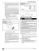
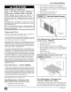
See Figure 8 and Figure 9 for side and bottom locations. Rack
end cap is similar for bottom mounted filter rack.
Filter rack(s) attached to the outside of the furnace is made so the
filter simply slides out one end for removal.
End cap
25-24-62-1
Filter Replacement - Bottom or Side
Mounted Filter Rack Outside Furnace
1. Turn OFF electric power to furnace.
2. Remove the end cap from the filter rack.
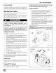
Filter Replacement - Horizontal and
Downflow *8MPN/L (Not *8DNL)
The filter may be installed at the inlet end of the blower compart-
ment, either inside or outside the furnace. Side inlet filter loca-
tions are not permitted for horizontal or downflow applications.
441 02 2010 04
Center Clip
side-to-side
25-24-18-1
Filter Replacement - Bottom Mounted Filter
Inside Furnace, (*8MPN/L)
1. Turn off electric power to furnace.
2. Remove blower door.
3. Slide filter straight out toward you. See Figure 9.
4. Inspect the filter(s) and replace or clean washable types. If
filter is aluminum mesh it should be recoated with filter
coating spray
5. Replace blower door.
6. Turn on electric power to furnace.
1 Bottom Mounted Filter InsideFurnace