
Installation guide

Requirements
1. Provide the space with sufficient air for proper combustion and
ventilation of flue gases using horizontal or vertical ducts or
openings.
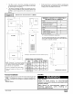
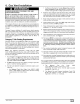
2. Figure 3 illustrates how to provide combustion and ventilation
air when two permanent openings, one inlet and one outlet, are
used.
a. One opening MUST commence within 12" of the floor and
the second opening MUST commence within 12" of the
ceiling.
b. Size openings and ducts per Table 1.
Outside Air (This is ONLY a guide. Subject to codes of country having jurisdiction.)
ThisinstallationNOTapprovedinCanada
/
GasVent • GableVent)
.,1'
;pace
MinimumOne Inletand OneOutlet AirSupply is Required
May be in andCombination Shown
Inlet AirOpeningMustbeWithin12"(300mm)of floor
OutletAir OpeningMustbe Within12"(300mm)of ceiling
(1) 1 SquareInch (6cm2) per 4000 BTUH
(2) 1 Square Inch(6cmz) per 2000 BTUH
Gas Vent j_Gable Vent
VentilatedAttic'S.
II " SoffitVent
SoffitVent J_utlet Air(1) Outle_
II _. Air(1) [_
I F...... _G%
Air (1) _' _ _ -- Inlet
-- Air (2) Inlet
Air(1)
-, i I I,n,e`
_ '_ _ _ Air (2)
c. Horizontal duct openings require I square inch of free area
per 2,000 BTUH (1,100 mmZ/kW) of combined input for all
gas appliances in the space (see Table 1).
d. Vertical duct openings or openings directlycommunicating
with the outdoors require 1 square inch of free area per
4,000 BTUH (550 mm2/kW) for combined input of all gas
appliances in the space (see Table 1).
3. When one permanent outdoor opening is used, the opening
requires:
a. 1 sq. in of free area per 3,000 BTUH (700 mm2/kW) for
combined input of all gas appliances in the space (see
Table 1) and
b. not less than the sum of the areas of all vent connectors in
the space.
The opening shall commence within 12" of the top of the enclo-
sure. Appliances shall have clearances of at least I "from the sides
and back and 6" from the front. The opening shall directly commu-
nicate with the outdoors or shall communicate through a vertical or
horizontal duct to the outdoors or spaces (crawl or attic) that freely
communicate with the outdoors.
4. Combination of Indoor and Outdoor Air shall have:
a.
b.
C.
Indoor openings that comply with the Indoor Combus-
tion Air Method below and
Outdoor openings located as required in the Outdoor
Combustion Air Method above and
Outdoor openings sized as follows.
1) Calculate the Ratio of all Indoor Space volume divided
by required volume for Indoor Combustion Air Method.
2) Outdoor opening size reduction Factor is 1 minus the
Ratio in 1) above.
3) Minimum size of Outdoor openings shall be the size re-
quired in Outdoor Combustion Air Method above multi-
plied by reduction Factor.
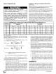
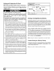
Area
BTUH MinimumFreeArea Requiredfor EachOpeningor Ductto Outdoors
TwoVerticalDuctsor RoundDuct
Input TwoHorizontalDucts SingleOpening Openings (sq. in./4,000
Rating (sq. in./2,000BTUH) (sq. in./3,000BTUH) (sq.in./4,000 BTUH) BTUH)
50,000 25sq. in. 16.7 sq. in, 12.5 sq. in, 4"
75,000 37,5sq. in. 25 sq. in. 1825 sq. in. 5"
100,000 50 sq, in. 33.3 sq.in, 25sq. in. 6"
125,000 62.50sq. in. 41.7 sq. in. 31.25 sq. in. 7"
150,000 75 sq. in. 50sq. in. 37.5 sq. in. 7"
EXAMPLE: Determining Free Area
Furnace Water Heater Total Input
100,000 + 30,000 (130,000 + 4,000) 32.5 Sq. In. Vertical
Furnace Water Heater Total Input
100,000 + 30,000 (130,000 + 2,000) 65 Sq. In. Horizontal
441 01 231402