
Installation guide
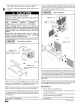


NOTE: It is very important to reinstall the NOx insert mounting Air Temperature Rise Check
screws.
iiiiiiiiiiiiiiiiiiiiiiiiiiiii_i_i!:!!!!i_!ill¸II¸II¸I¸;i;_i!i_i_i_i_ii!i!i!!!!!!i!_;_;_;_;_;_;_;_;_;_i_i!iiiiiiiiiiiiiii_iii!!_iiiiiiiii_i;;i_i_i!i!_!;;!iiiiii!_
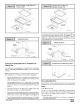
Removing NOx inserts
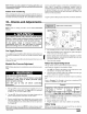
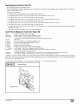
Main Burner Flame Check
Allow the furnace to run approximately 10 minutes. Then inspect
the main burner and pilot flames. See Figure 24.
Check for the following (Figure 24):
• Stable and blue flames. Dust may cause orange tips or wisps
of yellow, but flames MUST NOT have solid, yellow tips.
• Flames extending directly from burner into heat exchanger.
• Flames do NOT touch sides of heat exchanger
If any problems with main burner flames are noted, it may be nec-
essary to adjust manifold gas pressure, or check for drafts.
Main Burner
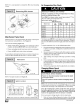
NOTE: For Ignitor location see Figure 25.
Ignitor Location
21/16
25-25-08
NOTE: Flame sensor has a different orientation in all 050 models.
REDUCED FURNACE LIFE HAZARD
Failure to properly set the air temperature rise may
result in reduced furnace life.
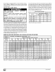
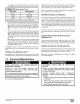
Use ONLY the blower motor speed taps marked "Y" for
YES for setting air temperature rise.
Blower Motor Speed Taps for
M HI HI
ModelSizes
ORN BLK
050B12 Y N
075B12 Y Y
075F16 Y Y
100F14 Y Y
100J20 Y Y
100L20 Y Y
125L20 Y Y
"8DNL ModelSizes
LO M LO
RED BLUE
N Y
N Y
N N
N N
N Y
Y Y
Y Y
The blower speed MUST be set to give the correct air temperature
rise through the furnace as marked on the rating plate. Tempera-
ture rise is the difference between supply and return air tempera-
tures.
To check temperature rise, use the following procedure:
1. Place thermometers in supply and return air registers as close
to furnace as possible, avoiding direct radiant heat from heat
exchangers.
2. Operate furnace for 10 minutes with all the registers and duct
dampers open by using a jumper wire on R to W thermostat
connections on the fan board.
3. Take readings and compare with range specified on rating
plate.
4. If the air temperature rise is not in the correct range, the blow-
er speed must be changed. A higher blower speed will lower
the temperature rise. A lower blower speed will increase the
temperature rise.
5. Remove the jumper wire after the adjustments are complete.
Changing Blower Speed
ELECTRICAL SHOCK HAZARD.
Failure to disconnect power could result in death
or personal injury.
Turn OFF power to furnace before changing speed
taps.
NOTE: The speed taps that the manufacturer sets at the factory
for this furnace are based on a nominal 400 CFM per ton cooling
and the basic mid range on the temperature rise for heating.
Since the manufacturer cannot predict the static pressure
that will be applied to the furnace, it is the responsibility of the
installer dealer/contractor to select the proper speed tap
leads for the application when the furnace is installed.
If it is necessary to change speeds, refer to steps below.
1. Refer to Furnace Hhking Diagram for location of the heating
and cooling speed taps located on the furnace control as well
441 01 2314 02