
Installation guide


NOTE: If filters are only suitable for heating application, ad-
vise homeowner that filter size may need to be increased if air
conditioning is added.
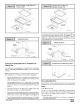
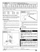
Addition Of Air Conditioning
When a refrigeration coil is used in conjunction with this furnace, it
must be installed on the discharge side of the furnace to avoid con-
densation on the heat exchanger. The coil installation instructions
must be consulted for proper coil location and installation proce-
dures. With a parallel flow arrangement, dampers must be
installed to prevent chilled air from entering the furnace. If ma nual-
ly operated dampers are used, they must be equipped with a
means to prevent operation of either unit unless the damper is in
full heat or full cool position.
Copper or plastic tubing may be used for the condensate drain line.
10. Checks and AdJustments
Startup
NOTE: Refer to startup procedures in the Users Information
Manual.
ELECTRICAL SHOCK, FIRE, OR EXPLOSION HAZRD.
Failure to follow safety warnings exactly could result
in death, personal injury, and/or property damage.
If any sparks, odors or unusual noises occur,
immediately shut OFF gas and power to furnace.
Check for wiring errors or obstruction to blower.
iiiiiiiil!!!!! ii¸I¸iiiiii_¸I¸ !!i!!iiil;;i;;iiiiiiiiiiiiiiii;iiiiiii
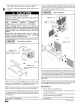
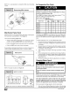
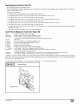
Typical Gas Control Valve
RegulatorAdjustment
UnderCa
Inlet
Pressure
Tap1/8NPT
HONEYWELL
©o
Outlet
Pressure
Tap
1/8NPT
/
OUTLET
25-24-98a
Gas SupplyPressure
Gas supply pressure should be within minimum and maximum val-
ues listed on rating plate. Pressures are usually set by gas suppli-
ers.
(See L.P. Gas Conversion Kit instruction manual for furnaces con-
verted to L.P. gas)
Manifold Gas Pressure Adjustment
NOTE: Make adjustment to manifold pressure with burners oper-
ating.
FIRE OR EXPLOSION HAZARD.
Failure to turn OFF gas at shut off before connecting
manometer could result in death, personal injury
and/or property damage.
Turn OFF gas at shut off before connecting
manometer.
1. With gas OFF, connect manometer to manifold pressure tap
on outlet of gas control valve. See Figure 20. Use a manome-
ter with a 0" to 12" water column range.
2.
3.
Turn gas ON. Operate the furnace by using a jumper wire on
the R to W thermostat connections on the control.
Remove manifold pressure adjustment screw cover on fur-
nace gas control valve. Turn screw counterclockwise to de-
crease manifold pressure and clockwise to increase pressure.
See Figure 20.
NOTE: Adjustment screw cover MUST be replaced on gas control
valve before reading manifold pressure and operating furnace.
441 01 231402
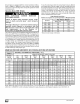
4. Set manifold pressure to value shown in Table 5 or Table 6.
5. When the manifold pressure is properly set, replace the adjust-
ment screw cover on the gas valve.
Remove jumper wire from thermostat connection on control.
Remove manometer connection from manifold pressure tap,
and replace plug in gas valve.
7. Check for leaks at plug.
Natural Gas Input Rating Check
The gas meter can be used to measure input to furnace.
Check with gas supplier for actual BTU content.
1. Turn OFF gas supply to all appliances other than furnace and
start furnace. Use jumper wire on R to W.
2. Time how many seconds it takes the smallest dial on the gas
meter to make one complete revolution.
Note: If meter uses a 2 cubic foot dial, divide results (seconds) by
two.
Refer to Example. The Example is based on a natural gas BTU
content of 1,000 BTU's per cubic foot.
Example
6.
Natural Gas No. of Seconds Time Per Cubic BTU Per
BTU Content Per Hour Foot in Hour
per cu, foot Seconds
1,000 3,600 48 75,000
1,000 x 3,600 + 48 = 75,000 BTUH
Refer to Example. The Example is based on a natural gas BTU
content of 1,000 BTU's per cubic foot.
3. Remove jumper wire from R to W.
4. Relight all appliances and ensure all pilots are operating.
Orifice Sizing
NOTE: Factory sized orifices for natural and LP gas are listed in
the furnace Technical Support Manual.