
Installation guide
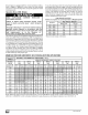


Disposable,lowvelocityfiltersarebasedonamaximumair
flowof300FPMwhenusedwithexternalfiltergrille.
i • See page 33, Circulation Air Blower Data for additional infor-
mation.
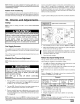
REDUCED FURNACE LIFE HAZARD
Failure to follow caution instructions may result in
reduced furnace life.
Use of excessively dirty and/or restrictive air filters
may increase furnace operating
temperatures and shorten the life of the furnace.
Filters supplied with the furnace are rated at a
maximum of 600 fpm air velocity and sized for the
furnace's airflow rate. Replacement filters must be of
equivalent type, size, and rating except as described
below.
Disposable, low-velocity filters may be used to
replace washable, high-velocity filters, providing
they are sized for 300 FPM or less.
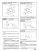
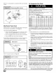
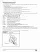
Filter Rack Installation
Version "A"
factory-attached to the
top of the blower housing
25-25-14a
OR
Version "B"
factory-supplied but field
installed
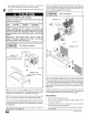
NOTE: The return air plenum MUST extend a sufficient height
above the furnace (dimension "A" in Figure 19) to provide for the
attachment of a return air duct or grille above the filters.
NOTE: Plenum must be fitted as close to the return air flange of the
furnace as possible to eliminate any air bypassing the filters.
Filters can only be installed through the right hand side of the fur-
nace blower opening. Slide filter into furnace until it is in position to
be pushed up and over into place on the left hand side of furnace.
See Figure 19.
Slide remaining filter into furnace and up into place on right hand
side of furnace. See Figure 19.
If there is insufficient plenum height for this type of installation, fil-
ters may be installed in any accessible location in the return air
system. In such a case, the filters should be of equivalent size and
style as originally supplied with the furnace.
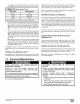
Filter Installation
Version "A'"
,,A,, l 14" (350mm)
25-25-14
OR
Version "B"
16"
(400mm)
The redesigned filter bracket needs to be centered on top of the
flanges spanning the depth of the flange opening. Position it sothe
"V" portion is between the inner sides of the flanges with the flat
tabs are resting on top of the flange edges. The tabs can then be
bent over the flanges on both ends by hand or by tapping lightly
with a hammer to secure the bracket to the top of the furnace. (see
Figure 18)
No further attachment is necessary. Once the plenum is attached
to the top of the furnace the bracket will not move. The bracket will
look like Figure 18 after being formed onto the flanges.
Filter Removal
1. Remove blower compartment door.
2. Reach up above right side of blower and lift dirty filters out of
rack at top of furnace.
3. Straighten up filters and pull straight down at side of blower.
Pull out through right door opening.
4. Vacuum clean or wash with warm water and dry thoroughly be-
fore replacing.
_] 441 O1 2314 02