
Installation guide

CARBON MONOXIDE POISONING HAZARD.
Failure to follow safety warning exactly could
result in death or personal injury.
Install cooling coil on furnace discharge. Cool air
passing over heat exchanger could cause
condensate to form resulting in heat exchanger
failure.
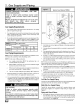
When the furnace is used with a cooling unit, the furnace shall
be installed parallel with or on the upstream side of the cooling
unit to avoid condensation in the heating element.
With a parallel flow arrangement, the dampers or other means
used to control flow of air shall be adequate to prevent chilled
air from entering the furnace. Chilled air going through the fur-
nace could cause condensation and shorten furnace life.
Dampers (purchased locally) can be either automatic or manu-
al. Manually or automatically operated dampers MUST be
equipped with a means to prevent furnace or air conditioning
operation, unless damper is in the full heat or cool position
Installation of locking-type dampers is recommended in all
branches, or in individual ducts to balance system's air flows.
Non-combustible, flexible duct connectors are recommended
for return and supply connections to furnace.
If air return grille is located close to the fan inlet, install at least
one, 90 ° air turn between fan and inlet grille to reduce noise.
• Ductwork installed in attic, or exposed to outside temperatures
requires a minimum of 2" of insulation with outdoor type vapor
barrier.
• Ductwork installed in an indoor unconditioned space requires
a minimum of 1" of insulation with indoor type vapor barrier.
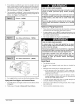
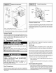
Inspection Panel on Some Models
For a furnace not equipped with a cooling coil, the outlet duct shall
be provided with a removable access panel. This opening shall be
accessible when the furnace is installed and shall be of such a size
that the heat excha nger can be viewed for possible openings using
light assistance or a probe can be inserted for sampling the air
stream. This access cover shall be attached in such a manner as
to prevent air leaks.
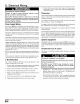
Sub-Bases for Combustible Floors - Furnace Only
The Subbase for Combustible Floors MUST be used when a
downflow furnace is set on a combustible floor, even when the fur-
nace is installed on a coil box.
NOTE: Supply opening is 37/8" from the rear of the furnace.
Therefore maintain a 37/8 ', clearance from a wall behind the fur-
nace (where applicable).
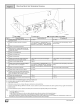
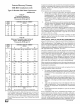
1. Cut the opening in the floor according to the dimensions in
Table 4 because the base is equipped with locating tabs that
center the base over the opening.
The opening in the base is 11/4" shorter and 11/8" narrower
than the minimum required size of the opening in the floor. This
is done to maintain a 1" clearance between the floor and the
plenum.
2. Fabricate the plenum to the dimensions given in Table 4. Note
that the dimensions given are outside dimensions.
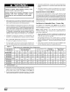
Table 4
Sub-bases for Combustible Floors Dimensions
N _
1511/16
195/16
24J/4
1511/16
195/16
24]]/16
sub-base for
Combustible Floors
Part Number
Furnace Only
NAHHOOISB
NAHHOO2SB
NAHHOIOSB
Subbase for Coil Box
NAHHOO4SB
NAHHOOSSB
NAHHOO9SB
Outside Dimension
_ Base Spacer Side To Side
3.
4,
sub-base for Combustible
Floor Dimensions
J* K**
283/4 149/16
283/4 183/16
28J/4 239/16
209/16 149/16
209/16 183/16
209/16 239/16
Opening In Floor
L M N
16 16114 14518
16 16114 18114
16 16]/4 235/8
16 161/4 145/8
16 161/4 181/4
16 16]/4 235/8
Opening In
Base For Plenum
Typical Plenum
Dimensions
15
15
15
P R
15 131/2
15 171/8
15 221/2
15 131/2
15 171/8
15 221/2
15
15
15
131/2
171/8
221/2
131/2
171/8
221/2
Set the base over the opening in the floor, centering the open-
ing in the base over the opening in the floor. Fasten the base to
the floor with screws or nails. See Figure 13 and Figure 14.
Drop the plenum through the opening in the base. The flange
of the plenum should rest on top of the combustible floor base.
_] 441 01 2314 02