
Installation guide

7. Gas Supply and Piping
CARBON MONOXIDE POISONING, FIRE AND
EXPLOSION HAZARD.
Failure to follow safety warnings exactly could
result in death, personal injury and/or property
damage.
Models designated for Natural Gas are to be used
with Natural Gas ONLY, unless properly
converted to use with LP gas.
Gas SupplyRequirements
• Use only the Type of gas approved for this furnace. See rating
plate for approved gas type.
• Gas input must not exceed the rated input shown on the rating
plate. Overfiring will result in failure of heat exchanger and
cause dangerous operation.
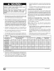
Do not allow minimum supply pressure to vary downward. Do-
ing so will decrease input to furnace. Refer to Table 3 for gas
supply. Refer to Table 5 or Table 6 for manifold pressures.
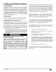
i I Pressures
Gas Type Supply Pressure
Recommended Max.
Natural 7" 14"
Propane 11" 14"
Min,
4,5"
11"
Gas Piping Requirements
NOTE: The gas supply line must be installed bya qualified service
technician in accordance with all building codes.
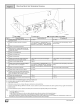
NOTE: In the state of Massachusetts.
1,
2.
a. Gas supply connections MUST be performed by a li-
censed plumber or gas fitter).
b. When flexible connectors are used, the maximum length
shall not exceed 36" (915 ram).
c. When lever handle type manual equipment shutoff valves
are used, they shall be T-handle valves.
d. The use of copper tubing for gas piping is NOT approved.
Install gas piping in accordance with local codes, or in the ab-
sence of local codes, the applicable national codes.
It is recommended that a manual equipment shutoff valve be
installed in the gas supply line outside the furnace. Locate
valve as close to the furnace as possible where it is readily ac-
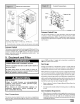
cessible. Refer to Figure 7.
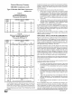
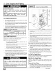
Typical Gas Piping ('8DNL)
Drip leg &
pipe cap _.
Listed Flexible
Gas Appliance
Connector if
11o4
IO]
Se_c%
union
\
Gas control
valve
Elbows & 25-25-17
short nipples
3. Use black iron or steel pipe and fittings or other pipe approved
by local code.
4. Use pipe thread compound which is resistant to natural and LP
gases.
5. Use ground joint unions and install a drip leg no less than 3"
long to trap dirt and moisture before it can enter gas control
valve inside furnace.
6. Provide a 118" NPT plugged tapping for test gauge connection
immediately up stream of gas supply connection to furnace.
7. Use two pipe wrenches when making connections to prevent
gas valve from turning.
NOTE: If local codes allow the use of a flexible gas appliance con-
nector, always use a new listed connector. Do not use a connector
which has previously served another gas appliance.
8. Flexible corrugated metal gas connector may NOT be used in-
side the furnace or be secured or supported by the furnace or
ductwork.
9. Properly size gas pipe to handle combined appliance load or
run gas pipe directly from gas meter or LP gas regulator.
10. Install correct pipe size for run length and furnace rating.
11. Measure pipe length from gas meter or LP second stage regu-
lator to determine gas pipe size.
Left Side Gas Supply Piping
Gas line can be installed directly to the gas valve through the hole
provided in the left side of the cabinet. See Figure 7
FIRE HAZARD
Failure to follow safety warnings exactly could
result in death, personal injury and/or property
damage.
Use wrench to hold furnace gas control valve when
turning elbows and gas line to prevent damage to the
gas control valve and furnace.
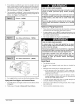
Right Side Gas Supply Piping
Two(2) 90 ° street elbows or two(2) 90 ° standard elbows and
two(2) close nipples are required for right side gas supply. See
Figure 7.
Piping with Street Elbows
1. Assemble the elbows so that the outlet of one(l) elbow is 90 °
from the inlet of the other. The elbows should be tight enough
to be leak proof. An additional 1/4 turn will be required at the
end of step 2, see Figure 8.
_] 441 01 2314 02