
Installation guide
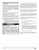
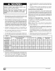

Exterior Masonry Chimney,
FAN+NAT Installations with
Type-B Double-Wall Vent Connectors
VENT
HEIGHT
(FT)
6
8
10
15
20
30
VENT
HEIGHT
(FT)
6
8
o 10
2O
30
_" 10
0
,_ 15
20
30
6
8
o 10
o is
i
2O
© NFPA& AGA
Table A-
Combined Appliance
Maximum Input Rating in
Thousands of Btu per Hr
INTERNAL AREA OF
(SQ IN.)
12 19 28
74 119 178
80 130 193
84 138 207
NR 152 233
NR NR 250
NR NR NR
CHIMNEY
Table B-
Minimum Allowable Input Rating of
Space-Heating Appliance in
Thousands of Btu per Hr
38
257
279
299
334
368
404
INTERNAL AREA OF CHIMNEY
(SQ IN.)
12 19 28 38
Local 99% Winter Design Temperature: 17 to 26 ° F*
0 55 99 141
52 74 111 154
NR 90 125 169
NR NR 167 212
NR NR 212 258
NR NR NR 362
Local 99% Winter Design Temperature: 5 to 16° F*
NR 78 121 166
NR 94 135 182
NR 111 149 198
NR NR 193 247
NR NR NR 293
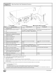
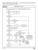
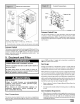
Inspections before the sale a nd at the time of installation will deter-
mine the acceptability of the chimney or the need for repair and/or
(re)lining. Refer to the Chimney Inspection Chart to perform a
chimney inspection.
If the inspection of a previously used tile-lined chimney:
a. Shows signs of vent gas condensation, the chimney should
be relined in accordance with local codes and the authority
having jurisdiction. The chimney should be relined with a
listed metal liner or Type-B vent to reduce condensation. If
a condensate drain is required by local code, refer to the
NEGC, Section 10.9 for additional information on conden-
sate drains.
b. Indicates the chimney exceeds the maximum permissible
size in the tables, the chimney should be rebuilt or relined to
conform to the requirements of the equipment being
installed and the authority having jurisdiction.
A chimney without a clay tile liner, which is otherwise in good con-
dition, shall be rebuilt to conform to AN SI/N FPA 211 or be lined with
a UL listed (ULC listed in Canada) metal liner or UL listed Type-B
vent. Relining with a listed metal liner or Type-B vent is consid-
ered to be a vent-in-a-chase.
If a metal liner or Type-B vent is used to line a chimney, no other
appliance shall be vented into the annular space between the
chimney and the metal liner.
APPLIANCE APPLICATION REQUIREMENTS
NR NR NR 377
Local 99% Winter Design Temperature: -10 to 4° F*
NR NR 145 196
NR NR 159 213
NR NR 175 231
NR NR NR 283
NR NR NR 333
NR NR NR NR
Appliance operation has a significant impact on the performance
of the venting system. If the appliances are sized, installed, ad-
justed, and operated properly, the venting system and/or the ap-
pliances should not suffer from condensation and corrosion. The
venting system and all appliances shall be installed in accordance
with applicable listings, standards, and codes.
30
-11 ° F Local 99% Winter Design Temperature: -11 ° F or
or lower*
lower Not recommended for any vent configuration
The 99% Winter Design Dry-Bulb (db) temperatures are found in the
1993 ASHRAE Fundamentals Handbook, Chapter 24, Table 1
(United States) and 2 (Canada), or use the 99.6% beating db temper-
atures found in the 1997 or 2001 ASHRAE Fundamentals Handbook,
Climatic Design Information chapter, Table 1A (United States) and 2A
(Canada).
The furnace should be sized to provide 100 percent of the design
heating load requirement plus any margin that occurs because of
furnace model size capacity increments. Heating load estimates
can be made using approved methods available from Air Condi-
tioning Contractors of America (Manual J); American Society of
Heating, Refrigerating, and Air-Conditioning Engineers; or other
approved engineering methods. Excessive oversizing of the fur-
nace could cause the furnace and/or vent to fail prematurely.
When a metal vent or metal liner is used, the vent or liner must be in
good condition and be installed in accordance with the vent or liner
manufacturer's instructions.
To prevent condensation in the furnace and vent system, the fol-
lowing precautions must be observed:
1. The return-air temperature must be at least 60°F db except
for brief periods of time during warm-up from setback at no
lower than 55°F db or during initial start-up from a standby
condition.
Adjust the gas input rate per the installation instructions.
Low gas input rate causes low vent gas temperatures, ca us-
ing condensation and corrosion in the furnace and/or vent-
ing system. Derating is permitted only for altitudes above
2000'.
3. Adjust the air temperature rise to the midpoint of the rise
range or slightly a hove. Low air temperature rise ca n ca use
low vent gas temperature and potential for condensation
problems.
4. Set the thermostat heat anticipator or cycle rate to reduce
short cycling.
Air for combustion must not be contaminated by halogen com-
pounds which include chlorides, fluorides, bromides, and iodides.
These compounds are found in many common home products
such as detergent, paint, glue, aerosol spray, bleach, cleaning sol-
vent, salt, and air freshener, and can cause corrosion of furnaces
and vents. Avoid using such products in the combustion-air sup-
441 01 2314 02