
Installation guide

SEQUENCE
OF
OPERATION
A.
COOLING
MODE
On
a
call
for
cooling,
the
thermostat
makes
circuits
R-O,
R-Y,
and
R-G.
Circuit
R-O
energizes
reversing
valve,
switching
it
to
cooling
position.
Circuit
R-Y
energizes
contactor,
starting
outdoor
fan
motor
and
compressor.
Circuit
R-G
energizes
indoor
unit
blower
relay,
starting
indoor
blower
motor.
When
thermostat
is
satisfied,
its
contacts
open,
de-energizing
contactor
and
blower
relay.
Compressor
and
motors
stop.
NOTE:
If
indoor
unit
is
equipped
with
a
time-delay
relay
circuit,
the
blower
runs
an
additional
length
of
time
to
increase
system
efficiency.
(Applies
to
both
cooling
and
heating
modes.)
TROUBLESHOOTING
B.
HEATING
MODE
On
a
call
for
heating,
the
thermostat
makes
circuits
R-Y
and
R-G
(circuit
R-O
is
NOT
made,
and
the
reversing
valve
stays
in
the
de-energized,
heating
position).
Circuit
R-Y
energizes
contactor,
starting
outdoor
fan
motor
and
compressor.
Circuit
R-G
energizes
indoor
blower
relay,
starting
blower
motor.
If
the
room
temperature
continues
to
fall,
circuit
R-W2
is
made
through
the
second-stage
room
thermostat
bulb.
Circuit
R-W2
energizes
a
sequencer,
bringing
on
the
first
bank
supplemental
electric
heat
and
providing
electrical
potential
to
the
second
heater
sequencer
(if
used).
If
outdoor
temperature
falls
below
the
setting
of
the
outdoor
thermostat
(field-installed
option),
contacts
close
to
complete
the
circuit
and
bring
on
the
second
bank
of
supplemental
electric heat.
When
the
thermostat
is
satisfied,
its
contacts
open,
de-energizing
contactor,
blower
relay,
and
sequencer.
Compressor,
motors,
and
heaters
stop.
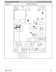
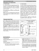
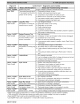
Some
models
are
factory
equipped
with the
Comfort
Alert™
Diagnostics
device
in
the
control
box
(refer
to
Figure
17).
Comfort
Alert
provides
around-the-clock
monitoring
for
common
electrical
problems,
compressor
defects,
and
broad
system
faults.
If
trouble
is
detected,
an
alert
code
is
displayed
with
a
flashing
LED
indicator.
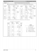
Alert
codes
are
listed
in
Figure
18.
The
device
is
factory
wired
and
requires
no
modification.
Low
voltage
lead
wires
are
provided
in
the
control
box
for
connection
to
thermostat
wires
(use
wire
nuts).
The
Comfort
Alert
device
operates
by
monitoring
the
compressor
power
leads
and
the
thermostat
demand
signal
(Y
terminal).
It
draws
constant
24
VAC
power
at
the
R
and
C
terminals.
MAINTENANCE
Comfort
Alert™
Diagnostics
Figure
17
(some
models)
Compressor
Wires
Pass
Through
Holes
(3)
~@—
“Power”
LED
<<
“Alert”
LED
<—
‘Trip’
LED
24
VAC
Hot
Condensate
Drain
During
the
cooling
season,
check
monthly
for
free
flow
of
drainage
and
clean
if
necessary.
Cleanliness
These
tips
will
help
keep
the
heat
pump
looking
better
and
working
more
efficiently:
1.
Free
flow
of
air
is
essential.
Keep
fences,
shrubs,
trash
cans,
and
other
obstructions
at
least
18
inches
(457mm)
from
all
coil
inlets.
2.
Keep
the
coil
free
of
grass
clippings,
leaves,
weeds,
and
other
debris.
NOTE:
Coil
may
occasionally
require
cleaning
with
a
liquid
solution.
The
coil
must
be
cold
when
cleaning.
Use
an
alkaline
based
cleaner
only.
Cleaning
a
hot
coil
or
using
an
acid
based
cleaner
will
remove
the
paint
from
the
fins
and
may
clog
the
coil.
3.
Never
use
a
weather
cover
over
the
outdoor
unit
unless
it
is
a
ventilated
type
or
made
of
breathable
fabric
that
will
allow
moisture
to
evaporate
rapidly.
A
cover
that
holds
moisture
in
the
unit
will
cause
more
rust
build-up
and
damage
than
normal
exposure
to
weather.
18
428
01
5103
02