
Owners manual


TPD/VPD Series HMI Device User Manual
Copyright © 2015 ICP DAS Co., Ltd. All Rights Reserved. Page: 25
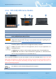
2.1.5 TPD-703/703-64 Series Models
\
1.
7” TFT LCD with Touch Panel
2.
Buzzer
3.
System LED Indicator
4.
Programmable LED Indicator
The System LED and Programmable LED is placed under the front cover of the TouchPAD device.
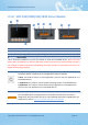
5.
Reset Button
The reset button is placed under the front cover of the TouchPAD device, please remove this cover
and use a flat-head screwdriver to press this button to reset the TouchPAD device. Note: The reset
button does not behave as a reboot to the whole system, only resets the microcontroller and this is
not enough to make the program downloading successful. Always cut the power then turn it on
before downloading programs.
6.
Rotary Switch (0 ~ 9)
The rotary switch is placed under the front cover of the TouchPAD device, please
remove this cover and use a flat-head screwdriver to set the configuration modes, as
follows:
0. Run & Update: This is a special run mode which is used in the development stage.
The TouchPAD device can be updated by a PC from the remote side through
Ethernet.
1. Force Update: While the application run on the TouchPAD device seriously crashes,
use this mode to update a new application to the TouchPAD device.
2. Run Only: Simply run, a TouchPAD device cannot be updated in this mode.