
Owners manual


TPD/VPD Series HMI Device User Manual
Copyright © 2015 ICP DAS Co., Ltd. All Rights Reserved. Page: 23
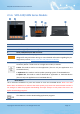
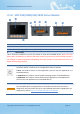
2.1.4 TPD-432F/433F Series Models
1.
4.3” TFT LCD with Touch Panel
2.
Buzzer
3.
Programmable LED Indicator
The Programmable LED is placed under the front cover of the TouchPAD device.
4.
Reset Button
The reset button is placed under the front cover of the TouchPAD device, please remove this cover
and use a flat-head screwdriver to press this button to reset the TouchPAD device. Note: The reset
button does not behave as a reboot to the whole system, only resets the microcontroller and this is
not enough to make the program downloading successful. Always cut the power then turn it on
before downloading programs.
5.
PoE and Ethernet RJ-45 Jack (for TPD-433F only)
The TouchPAD device is equipped with an RJ-45 jack that is used as the 10/100 Base-TX
Ethernet port and features networking capabilities. When an Ethernet link is detected
and an Ethernet packet is received, the Act LED (Green) indicator will be illuminated.
When power is supplied via PoE (Power-over-Ethernet), the PoE LED (Orange) indicator
will be illuminated.
6.
Power/GND/RS-485/RS-232 Connector
The TouchPAD device is equipped with a removable terminal block connector is
designed for easy and robust wiring. For more detailed information regarding the pin
assignments, refer to Section 2.2.2 TPD-432F/433F Series Models.