
User Manual


7521/2/2A/3/4/7 Series Hardware User’s Manual, Ver. 1.5 Sep/2002, 7Mh-001-15 -----12
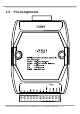
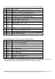
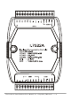
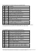
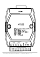
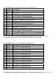
Pin assignment of 13-pin screw terminal block(7521/7521D):
Pin Name Description
1 X3 Connects to I/O expansion board
2 X2 Connects to I/O expansion board
3 X1 Connects to I/O expansion board
4 DO3 Digital output, 150mA, 30V
5 DO2 Digital output, 150mA, 30V
6 DO1 Digital output, 150mA, 30V
7 DI3 Digital input, 3.5V ~ 30V
8 DI2 Digital input, 3.5V ~ 30V
9 DI1/
INIT*
Initial pin or digital input, 3.5V ~ 30V
10 D2+ DATA+ pin of COM2 (RS-485)
11 D2- DATA- pin of COM2 (RS-485)
12 +VS V+ of power supply (+10 to +30VDC unregulated)
13 GND GND of power supply
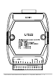
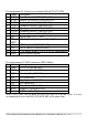
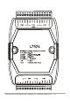
Pin assignment of COM1 connector (DB-9 Male):
Pin Name Description
1 Data+ DATA+ of RS-485 port
2 TXD Transmits Data (RS-232)
3 RXD Receives Data (RS-232)
4 N/C No Connection
5 GND Signal ground of RS-232
6 N/C No Connection
7 CTS Clear To Send (RS-232)
8 RTS Request To Send (RS-232)
9 Data- DATA- of RS-485 port
Note: The COM1 can be used as s RS-232 port or s RS-485 port. It is not
recommended to use both RS-232 & RS-485 at the same time.