
User's Manual

I-8091 User Manual Version 1.0 06/2001
http://www.icpdas.com 2-11 ICPDAS
2.4 Hardware Configuration
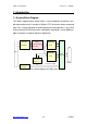
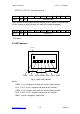
2.4.1 Limit switch configuration
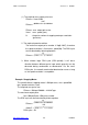
Because the profile generation and protection is executed by the CPU
on I-8091 card, the limit switches must configure as following diagram.
The motion command just can work properly.
LS11
ORG1
LS14
CW/FW
CCW/BW
Motor
EXT_GND
/LS11
/LS14
/ORG1
X axis
/EMG
Emer gency
ccm
Fig.(5) Limit switch configuration of X axis
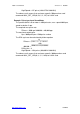
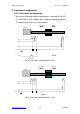
LS21
ORG2
LS24
CW/FW
CCW/BW
Motor
EXT_GND
/LS21
/LS24
/ORG2
Y axis
ccm
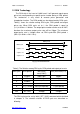
Fig.(6) Limit switch configuration of Y axis